Lexus NX: Hood Support
Components
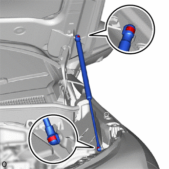
COMPONENTS
ILLUSTRATION
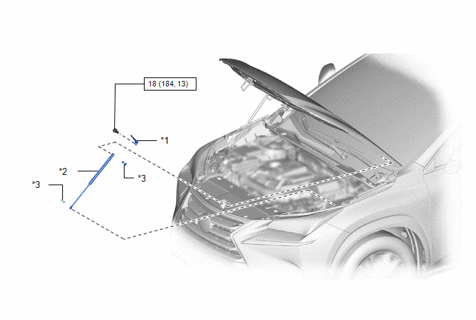
| *1 | HOOD STAY BRACKET LH | *2 | HOOD SUPPORT ASSEMBLY |
| *3 | STOP RING | - | - |
.png) | N*m (kgf*cm, ft.*lbf): Specified torque | - | - |
Removal
REMOVAL
CAUTION / NOTICE / HINT
HINT:
- Use the same procedure for both the RH and LH side.
- The procedure described below is for the LH side.
PROCEDURE
1. REMOVE HOOD SUPPORT ASSEMBLY
NOTICE:
- Avoid touching the piston rod as much as possible to prevent foreign matter from attaching to it. Be sure to hold the cylinder while servicing.
- Do not wear cotton gloves or other similar materials when handling the piston rod. Fibers may attach to the rod and result in gas leaks.
- Do not push sideways on the cylinder because the rod may bend.
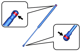
| (a) Using a thin-bladed screwdriver with its tip wrapped in protective tape, remove the 2 stop rings along their grooves. HINT: Tape the thin-bladed screwdriver tip before use. |
|
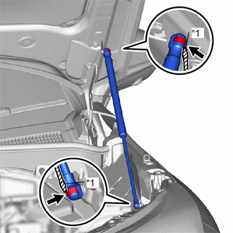
(b) Detach the 2 ball joints and remove the hood support assembly.
NOTICE:
Remove the hood support assembly while holding the hood by hand.
2. REMOVE HOOD STAY BRACKET LH
| (a) Remove the bolt. |
|
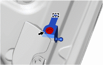
(b) Detach the guide and remove the hood stay bracket LH.
Installation
INSTALLATION
CAUTION / NOTICE / HINT
HINT:
- Use the same procedure for both the RH and LH side.
- The procedure described below is for the LH side.
PROCEDURE
1. INSTALL HOOD STAY BRACKET LH
(a) Attach the guide to install the hood stay bracket LH with the bolt.
Torque:
18 N·m {184 kgf·cm, 13 ft·lbf}
2. INSTALL HOOD SUPPORT ASSEMBLY
NOTICE:
- Avoid touching the piston rod as much as possible to prevent foreign matter from attaching to it. Be sure to hold the cylinder while servicing.
- Do not wear cotton gloves or other similar materials when handling the piston rod. Fibers may attach to the rod and result in gas leaks.
- In order to prevent the piston rod from deforming, do not apply any horizontal load to the door stay.
(a) When reusing the hood support assembly:
| (1) Install the hood support assembly with the 2 stop rings. |
|
| (b) Attach the 2 ball joints to install the hood support assembly. NOTICE:
|
|
Disposal
DISPOSAL
PROCEDURE
1. DISPOSE OF HOOD SUPPORT ASSEMBLY
(a) Horizontally hold the hood support in a vise with the piston rod pulled out.
| (b) Wear safety glasses. Gradually cut a part between A and B shown in the illustration using a metal saw to release the gas.
NOTICE: Although the gas inside the hood support is colorless, odorless and harmless, there is a possibility that metal debris could scatter. Therefore, cover it with a piece of cloth or other material. |
|
.png)
READ NEXT:
 Components
COMPONENTS ILLUSTRATION *1 KICK DOOR CONTROL BRACKET *2 KICK DOOR CONTROL SENSOR
Removal
REMOVAL PROCEDURE 1. REMOVE REAR BUMPER COVER Click here 2. REMOVE KICK DOOR CONTROL BRACKET (a) Disconnect the connector and detach the 2 wire harness clamps. NOTICE: Do not touch the terminal o
SEE MORE:
Blind Spot Monitor Sensor Communication Stop Mode
DESCRIPTION Detection Item Symptom Trouble Area Blind Spot Monitor Sensor Communication Stop Mode Any of the following conditions are met:
Communication stop for "Blind Spot Monitor Master" is indicated on the "Communication Bus Check" screen of the Techstream.
Click here
Commu
Vehicle Control History
VEHICLE CONTROL HISTORY NOTICE: When checking the Vehicle Control History, make sure to record the output codes. Then, clear the Vehicle Control History (RoB) and check it again. CHECK VEHICLE CONTROL HISTORY (FRONT RADAR SENSOR SYSTEM) (a) Connect the Techstream to the DLC3. (b) Turn the power swit
