Lexus NX: Components
COMPONENTS
ILLUSTRATION
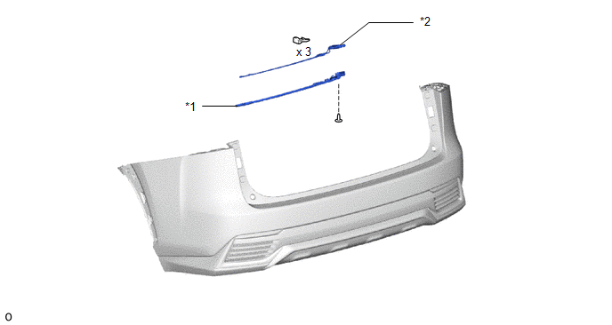
| *1 | KICK DOOR CONTROL BRACKET | *2 | KICK DOOR CONTROL SENSOR |
READ NEXT:
 Removal
REMOVAL PROCEDURE 1. REMOVE REAR BUMPER COVER Click here 2. REMOVE KICK DOOR CONTROL BRACKET (a) Disconnect the connector and detach the 2 wire harness clamps. NOTICE: Do not touch the terminal o
Installation
INSTALLATION PROCEDURE 1. INSTALL KICK DOOR CONTROL SENSOR (a) Insert the guide, attach the 2 claws and install the kick door control sensor to the kick door control bracket as shown in the illustr
Power Back Door Control Switch
ComponentsCOMPONENTS ILLUSTRATION *1 BACK DOOR CONTROL SWITCH *2 PULL HANDLE RemovalREMOVAL PROCEDURE 1. REMOVE PULL HANDLE Click here 2. REMOVE BACK DOOR CONTROL SWITCH (a) Detach
SEE MORE:
Fail-safe Chart
FAIL-SAFE CHART MALFUNCTION DETECTION (a) Operation when malfunction is detected Content Operation Heater failure Overcurrent detection of drive element Heater output off Overheating detection of drive element Heater output off Power failure Low-voltage detection Heater ou
Skid Control ECU Communication Stop Mode
DESCRIPTION Detection Item Symptom Trouble Area Skid Control ECU Communication Stop Mode Any of the following conditions are met:
Communication stop for "Skid Control (ABS/VSC/TRAC)" is indicated on "Communication Bus Check".
Click here
Communication system DTCs (DTCs that star
© 2016-2026 Copyright www.lexunx.com
