Lexus NX: Removal
REMOVAL
PROCEDURE
1. REMOVE REAR BUMPER COVER
Click here .gif)
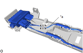
2. REMOVE KICK DOOR CONTROL BRACKET
| (a) Disconnect the connector and detach the 2 wire harness clamps. NOTICE: Do not touch the terminal of the kick door control sensor connector. |
|
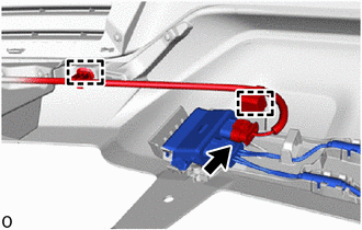
| (b) Remove the screw. |
|
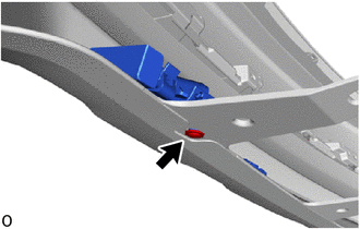
(c) Remove the 3 outside moulding retainers.
(d) Detach the 3 guides and remove the kick door control bracket together with the kick door control sensor as shown in the illustration.
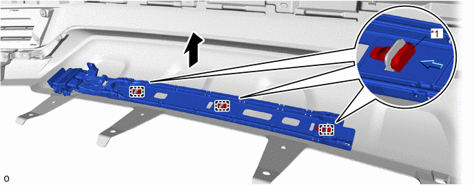
| *1 | Outside Moulding Retainer | - | - |
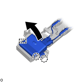
3. REMOVE KICK DOOR CONTROL SENSOR
(a) Detach the 16 claws in the order shown in the illustration and disconnect the antenna.
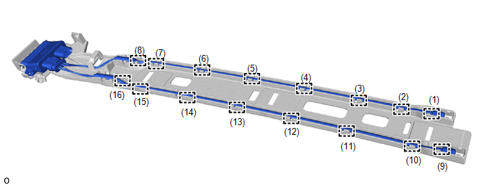
| (b) Detach the clamp and disconnect the wire (red) from the kick door control bracket. NOTICE:
|
|
| (c) Detach the 2 claws and guide, and remove the kick door control sensor from the kick door control bracket as shown in the illustration. NOTICE:
|
|
READ NEXT:
 Installation
INSTALLATION PROCEDURE 1. INSTALL KICK DOOR CONTROL SENSOR (a) Insert the guide, attach the 2 claws and install the kick door control sensor to the kick door control bracket as shown in the illustr
Power Back Door Control Switch
ComponentsCOMPONENTS ILLUSTRATION *1 BACK DOOR CONTROL SWITCH *2 PULL HANDLE RemovalREMOVAL PROCEDURE 1. REMOVE PULL HANDLE Click here 2. REMOVE BACK DOOR CONTROL SWITCH (a) Detach
SEE MORE:
Open in Bus 3 Main Bus Line
DESCRIPTION There may be an open circuit in one of the CAN main bus lines when the resistance between terminals 6 (CA3H) and 21 (CA3L) of the central gateway ECU (network gateway ECU) is 70 Ω or higher. Symptom Trouble Area
Resistance between terminals 6 (CA3H) and 21 (CA3L) of the cent
Removal
REMOVAL PROCEDURE 1. DISABLE AUTOAWAY/RETURN FUNCTION (for Power Tilt and Power Telescopic Steering Column) (a) Disable the autoaway/return function by changing the customize parameter. Click here CAUTION: Record the current customize parameter setting (whether the autoaway/return function is enab
