- VL-Voltage before Boosting
- Power Resource VB
Lexus NX: Hybrid Battery Precharge Contactor Circuit Stuck Closed (P0AE2-773)
Lexus NX Service Manual / Engine & Hybrid System / 2ar-fxe (hybrid / Battery Control) / Hybrid Control System / Hybrid Battery Precharge Contactor Circuit Stuck Closed (P0AE2-773)
DTC SUMMARY
MALFUNCTION DESCRIPTION
The hybrid vehicle control ECU detects a stuck closed malfunction of a precharge relay stuck malfunction on the HV battery negative side.
The cause of this malfunction may be one of the following:
Inside of inverter voltage sensor (VH) circuit malfunction
- Voltage sensor (VH) malfunction
- Motor generator control ECU (MG ECU) malfunction
- Communication (wire harness) malfunction
High voltage system malfunction
- Hybrid battery junction block assembly malfunction
DESCRIPTION
Refer to the description for DTC P0AE6-225.
Click here .gif)
| DTC No. | Detection Item | DTC Detection Condition | Trouble Area | MIL | Warning Indicate |
|---|---|---|---|---|---|
| P0AE2-773 | Hybrid Battery Precharge Contactor Circuit Stuck Closed | SMRP (precharge relay) is stuck closed due to a mechanical malfunction or other malfunction. (2 trip detection logic) |
| Does not come on | Master Warning Light: Comes on |
| DTC No. | Data List |
|---|---|
| P0AE2-773 | |
The following items can be helpful when performing repairs:
Data List
- SMRP Status
- SMRB Status
- SMRG Status
WIRING DIAGRAM
Refer to the wiring diagram for the HV battery high-voltage line circuit.
Click here
CAUTION / NOTICE / HINT
CAUTION:
- When troubleshooting DTC P0AE2-773, use either a tool wrapped with vinyl insulation tape or an insulated tool. (It is extremely dangerous when a high-voltage charge passes through a non-insulated tool causing a short.)
- Before inspecting the high-voltage system or disconnecting the low voltage connector of the inverter with converter assembly, take safety precautions such as wearing insulated gloves and removing the service plug grip to prevent electrical shocks. After removing the service plug grip, put it in your pocket to prevent other technicians from accidentally reconnecting it while you are working on the high-voltage system.
-
After removing the service plug grip, wait for at least 10 minutes before touching any of the high-voltage connectors or terminals. After waiting for 10 minutes, check the voltage at the terminals in the inspection point in the inverter with converter assembly. The voltage should be 0 V before beginning work.
Click here
HINT:
Waiting for at least 10 minutes is required to discharge the high-voltage capacitor inside the inverter with converter assembly.
NOTICE:
After turning the power switch off, waiting time may be required before disconnecting the cable from the negative (-) auxiliary battery terminal. Therefore, make sure to read the disconnecting the cable from the negative (-) auxiliary battery terminal notices before proceeding with work.
Click here
HINT:
After the repair, clear the DTCs, perform the following procedure and check that the same DTC (including pending DTC) is not output.
- Turn the power switch off and wait for 30 seconds or more.
- Turn the power switch on (READY) and wait for 30 seconds or more.
- Turn the power switch off and wait for 60 seconds or more.
PROCEDURE
| 1. | CHECK DTC OUTPUT (HYBRID CONTROL) |
(a) Connect the Techstream to the DLC3.
(b) Turn the power switch on (IG).
(c) Enter the following menus: Powertrain / Hybrid Control / Trouble Codes.
(d) Check for DTCs.
Powertrain > Hybrid Control > Trouble Codes| Result | Proceed to |
|---|---|
| P0AE2-773 only is output, or DTCs except the ones in the table below are also output. | A |
| Any of the following DTCs including pending DTCs are also output. | B |
| Malfunction Content | Relevant DTC | |
|---|---|---|
| Microcomputer malfunction | P0A1A-151, 658, 791 | Generator Control Module |
| P0A1B-786, 794 | Drive Motor "A" Control Module | |
| P0A1D-148 | Hybrid Powertrain Control Module | |
| P1C2A-155 | Generator A/D Converter Circuit | |
| P1CA6-156 | Generator Control Module Malfunction | |
| P1CA7-193 | Drive Motor Control Module Malfunction | |
| P1CAC-200 | Generator Position Sensor Angle Malfunction | |
| P1CAD-168 | Drive Motor "A" Position Sensor Angle Malfunction | |
| P1CAF-792 | Generator Position Sensor REF Signal Cycle Malfunction | |
| P1CB0-795 | Drive Motor "A" Position Sensor REF Signal Cycle Malfunction | |
| P1CB2-793 | Generator Position Sensor REF Signal Stop Malfunction | |
| P1CB3-796 | Drive Motor "A" Position Sensor REF Signal Stop Malfunction | |
| P2511-149 | HV CPU Power Relay Sense Circuit Intermittent No Continuity | |
| P3133-659 | Communication Error from Generator to Drive Motor "A" | |
| P3134-661 | Communication Error from Drive Motor "A" to Generator | |
| P324E-788 | MG-ECU Power Relay Intermittent Circuit | |
| Power source circuit malfunction | P06B0-163 | Sensor Power Supply "A" Circuit / Open |
| P06D6-511 | Sensor Reference Voltage "F" Circuit / Open | |
| P06E6-164 | Sensor Power Supply "C" Circuit / Open | |
| P1C73-512 | Sensor Standard Voltage "F" Circuit / Open | |
| Communication system malfunction | U0110 (all INF codes)*1 | Lost Communication with Drive Motor Control Module "A" |
| Sensor and actuator circuit malfunction | P0A3F-243 | Drive Motor "A" Position Sensor Circuit |
| P0A40-500 | Drive Motor "A" Position Sensor Circuit Range / Performance | |
| P0A41-245 | Drive Motor "A" Position Sensor Circuit Low | |
| P0A4B-253 | Generator Position Sensor Circuit | |
| P0A4C-513 | Generator Position Sensor Circuit Range / Performance | |
| P0A4D-255 | Generator Position Sensor Circuit Low | |
| P0AE0-228 | Hybrid Battery Negative Contactor Control Circuit High | |
| P0AE7-224 | Hybrid Battery Precharge Contactor Control Circuit High | |
| P0C76-523 | Hybrid Battery System Discharge Time Too Long | |
| System malfunction | P0AA4-232 | Hybrid Battery Negative Contactor Circuit Stuck Closed |
| P0CA3-442 | DC/DC Converter Step Up Voltage Performance | |
| P0D2E-586 | Drive Motor "A" Inverter Voltage Sensor Circuit Range / Performance | |
| P0D2F-266 | Drive Motor "A" Inverter Voltage Sensor Circuit Low | |
| P0D30-267 | Drive Motor "A" Inverter Voltage Sensor Circuit High | |
| P3004-132 | High Voltage Power Resource | |
HINT:
- *1: If any INF codes are output for this DTC, refer to the corresponding diagnostic procedure.
-
P0AE2-773 may be output as a result of the malfunction indicated by the DTCs above.
- The chart above is listed in inspection order of priority.
- Check DTCs that are output at the same time by following the listed order. (The main cause of the malfunction can be determined without performing unnecessary inspections.)
(e) Turn the power switch off.
| B | .gif) | GO TO DTC CHART (HYBRID CONTROL SYSTEM) |
|
.gif)
| 2. | CHECK FREEZE FRAME DATA (HYBRID CONTROL) |
(a) Connect the Techstream to the DLC3.
(b) Turn the power switch on (IG).
(c) Enter the following menus: Powertrain / Hybrid Control / Trouble Codes.
(d) Read the freeze frame data of DTC P0AE2-773.
HINT:
In the freeze frame data, read the item "VL-Voltage before Boosting".
| Result | Proceed to |
|---|---|
| "VL-Voltage before Boosting" is 55 V or more. | A |
| "VL-Voltage before Boosting" is less than 55 V. | B |
HINT:
If VH-Voltage after Boosting is output even when an off command is being sent to the system main relay (positive side), P0AE2-773 is output. If the difference between the "VL-Voltage before Boosting" and the "VH-Voltage after Boosting" is large, it is determined that there is an inverter (VH sensor) malfunction.
(e) Turn the power switch off.
| B | | REPLACE INVERTER WITH CONVERTER ASSEMBLY |
|
| 3. | CHECK CONNECTOR CONNECTION CONDITION (HYBRID VEHICLE CONTROL ECU CONNECTOR) |
Click here
| OK | | GO TO STEP 5 |
|
| 4. | CONNECT SECURELY |
|
| 5. | CHECK CONNECTOR CONNECTION CONDITION (FLOOR WIRE CONNECTOR) |
Click here
| OK | | GO TO STEP 7 |
|
| 6. | CONNECT SECURELY |
|
| 7. | CHECK CONNECTOR CONNECTION CONDITION (NO. 2 HYBRID BATTERY PACK WIRE CONNECTOR) |
Click here
| Result | Proceed to |
|---|---|
| OK | A |
| NG (The connector is not connected securely.) | B |
| NG (The terminals are not making secure contact or are deformed, or water or foreign matter exists in the connector.) | C |
| A | | GO TO STEP 10 |
| C | | GO TO STEP 9 |
|
| 8. | CONNECT SECURELY |
| NEXT | | GO TO STEP 10 |
| 9. | REPAIR OR REPLACE HARNESS OR CONNECTOR |
|
| 10. | CHECK CONNECTOR CONNECTION CONDITION (HYBRID BATTERY JUNCTION BLOCK ASSEMBLY CONNECTOR) |
Click here
| OK | | GO TO STEP 12 |
|
| 11. | CONNECT SECURELY |
|
| 12. | CHECK GROUND WIRE CONNECTION CONDITION (SMR ACTIVATION LOW-VOLTAGE CIRCUIT) |
Click here
| OK | | GO TO STEP 14 |
|
| 13. | CONNECT SECURELY |
|
| 14. | CHECK HARNESS AND CONNECTOR (HYBRID VEHICLE CONTROL ECU - HYBRID BATTERY JUNCTION BLOCK ASSEMBLY) |
CAUTION:
Be sure to wear insulated gloves.
(a) Check that the service plug grip is not installed.
NOTICE:
After removing the service plug grip, do not turn the power switch on (READY), unless instructed by the repair manual because this may cause a malfunction.
(b) Remove the No. 2 hybrid vehicle battery shield reinforcement.
Click here
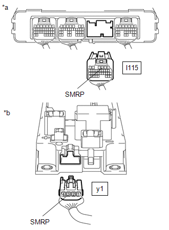
(c) Disconnect the y1 hybrid battery junction block assembly connector.
(d) Disconnect the I115 hybrid vehicle control ECU connector.
| (e) Measure the resistance according to the value(s) in the table below. Standard Resistance (Check for Open):
Standard Resistance (Check for Short):
|
|
(f) Reconnect the I115 hybrid vehicle control ECU connector.
(g) Reconnect the y1 hybrid battery junction block assembly connector.
(h) Install the No. 2 hybrid vehicle battery shield reinforcement.
| OK | | GO TO STEP 16 |
|
| 15. | REPAIR OR REPLACE HARNESS OR CONNECTOR |
|
| 16. | CHECK HARNESS AND CONNECTOR (HYBRID BATTERY JUNCTION BLOCK ASSEMBLY - BODY GROUND) |
Click here
| OK | | GO TO STEP 18 |
|
| 17. | REPAIR OR REPLACE HARNESS OR CONNECTOR |
|
| 18. | INSPECT HV BATTERY JUNCTION BLOCK ASSEMBLY (SMRP) |
CAUTION:
Be sure to wear insulated gloves.
(a) Check that the service plug grip is not installed.
NOTICE:
After removing the service plug grip, do not turn the power switch on (READY), unless instructed by the repair manual because this may cause a malfunction.
(b) Remove the No. 2 hybrid vehicle battery shield reinforcement.
Click here
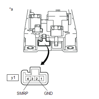
(c) Disconnect the y1 hybrid battery junction block assembly connector.
| (d) Measure the resistance according to the value(s) in the table below. Standard Resistance:
|
|
(e) Reconnect the y1 hybrid battery junction block assembly connector.
(f) Install the No. 2 hybrid vehicle battery shield reinforcement.
| NG | | GO TO STEP 21 |
|
| 19. | CHECK HV BATTERY JUNCTION BLOCK ASSEMBLY (SMRP) |
CAUTION:
Be sure to wear insulated gloves.
(a) Check that the service plug grip is not installed.
NOTICE:
After removing the service plug grip, do not turn the power switch on (READY), unless instructed by the repair manual because this may cause a malfunction.
(b) Remove the No. 2 hybrid vehicle battery shield reinforcement.
Click here
(c) Disconnect the 2 high voltage cable connectors of the HV battery from the hybrid battery junction block assembly.
(d) Disconnect the No. 2 frame wire from the hybrid battery junction block assembly.
(e) Measure the resistance according to the value(s) in the table below.
| (f) Measure the resistance according to the value(s) in the table below. Standard Resistance:
HINT:
|
|
(g) Reconnect the 2 high voltage cable connectors of the HV battery.
(h) Reconnect the No. 2 frame wire to the hybrid battery junction block assembly.
(i) Install the No. 2 hybrid vehicle battery shield reinforcement.
| NG | | GO TO STEP 22 |
|
| 20. | REPLACE HV BATTERY JUNCTION BLOCK ASSEMBLY |
Click here
| NEXT | | GO TO STEP 23 |
| 21. | REPLACE HV BATTERY JUNCTION BLOCK ASSEMBLY |
Click here
| NEXT | | GO TO STEP 23 |
| 22. | REPLACE HV BATTERY JUNCTION BLOCK ASSEMBLY |
Click here
|
| 23. | CHECK HYBRID VEHICLE CONTROL ECU (CHECK FOR NORMAL OPERATION) |
Click here
| Result | Proceed to |
|---|---|
| Difference between "Power Resource VB" and "VL-Voltage before Boosting" is always less than 100 V. | A |
| Difference between "Power Resource VB" and "VL-Voltage before Boosting" is 100 V or more. | B |
| A | | END |
| B | | REPLACE HYBRID VEHICLE CONTROL ECU AND HYBRID BATTERY JUNCTION BLOCK ASSEMBLY |
READ NEXT:
 Drive Motor Inverter Temperature Sensor "A" Circuit Low (P0AEF-275,P0AF0-274)
DESCRIPTION The MG ECU, which is built into in the inverter with converter assembly, detects the temperature of the motor inverter using a temperature sensor built into the inverter with converter ass
Sensor of Rear Motor Inverter Temperature (P0AF3-676,P0AF6-675)
DTC SUMMARY MALFUNCTION DESCRIPTION These DTCs indicate the temperature sensor value for rear motor inverter is abnormal. The cause of this malfunction may be one of the following: Internal inverter
Hybrid Battery Pack Sensor Module (P0AFC-150)
DESCRIPTION The hybrid vehicle control ECU alerts the driver and performs fail-safe control based on error signals sent from the battery voltage sensor. DTC No. Detection Item DTC Detection Con
SEE MORE:
How To Proceed With Troubleshooting
CAUTION / NOTICE / HINT HINT:
Use the following procedures to troubleshoot the power mirror control system.
*: Use the Techstream.
PROCEDURE 1. VEHICLE BROUGHT TO WORKSHOP
NEXT 2. CUSTOMER PROBLEM ANALYSIS CHECK HINT:
In troubleshooting, confirm that the
Parts Location
PARTS LOCATION ILLUSTRATION *1 FRONT ABSORBER CONTROL ACTUATOR RH (FRONT SHOCK ABSORBER ASSEMBLY RH) *2 FRONT ABSORBER CONTROL ACTUATOR LH (FRONT SHOCK ABSORBER ASSEMBLY LH) *3 REAR ABSORBER CONTROL ACTUATOR RH (REAR SHOCK ABSORBER ASSEMBLY RH) *4 REAR ABSORBER CONTROL ACTUATOR L
© 2016-2026 Copyright www.lexunx.com
