Lexus NX: Id Code Box
Components
COMPONENTS
ILLUSTRATION
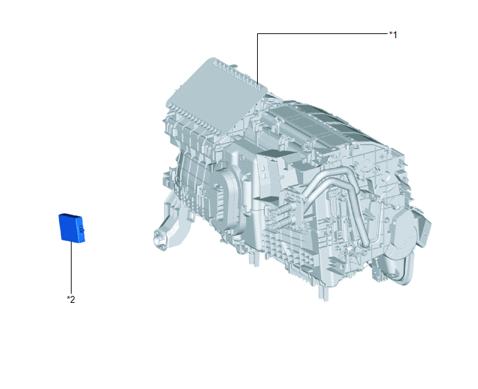
| *1 | AIR CONDITIONER UNIT ASSEMBLY | *2 | ID CODE BOX (IMMOBILIZER CODE ECU) |
Installation
INSTALLATION
PROCEDURE
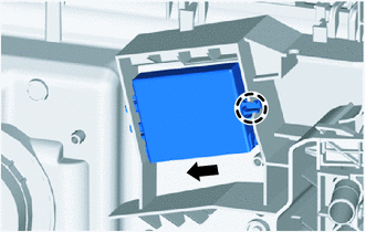
1. INSTALL ID CODE BOX (IMMOBILIZER CODE ECU)
(a) Attach the 2 guides.
(b) Attach the claw as shown in the illustration to install the ID code box (immobiliser code ECU).
2. INSTALL AIR CONDITIONER UNIT ASSEMBLY
Click here .gif)
3. CONNECT CABLE TO NEGATIVE AUXILIARY BATTERY TERMINAL
4. INITIALIZATION AFTER RECONNECTING AUXILIARY BATTERY TERMINAL
Click here
HINT:
When disconnecting and reconnecting the auxiliary battery, there is an automatic learning function that completes learning when the respective system is used.
Click here
5. REGISTER ECU CODE
Click here
Removal
REMOVAL
PROCEDURE
1. PRECAUTION
CAUTION:
Be sure to read Precaution thoroughly before serving.
Click here .gif)
NOTICE:
After turning the power switch off, there may be a waiting time before disconnecting the negative (-) auxiliary battery terminal.
Click here
2. DISCONNECT CABLE FROM NEGATIVE AUXILIARY BATTERY TERMINAL
CAUTION:
- Wait at least 90 seconds after disconnecting the cable from the negative (-) auxiliary battery terminal to disable the SRS system.
- If the airbag deploys for any reason. it may cause a serious accident.
3. REMOVE AIR CONDITIONER UNIT ASSEMBLY
Click here
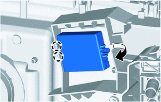
4. REMOVE ID CODE BOX (IMMOBILIZER CODE ECU)
| (a) Detach the claw as shown in the illustration. |
|
| (b) Detach the 2 guides and remove the ID code box (immobiliser code ECU). |
|
READ NEXT:
 Precaution
PRECAUTION PRECAUTION FOR DISCONNECTING CABLE FROM NEGATIVE AUXILIARY BATTERY TERMINAL NOTICE:
After the power switch is turned off, there may be a waiting time before disconnecting the negative (-
Parts Location
PARTS LOCATION ILLUSTRATION *1 NO. 1 ENGINE ROOM RELAY BLOCK AND NO. 1 JUNCTION BLOCK ASSEMBLY - AM2 FUSE - STRG LOCK FUSE *2 NO. 2 ENGINE ROOM RELAY BLOCK AND NO. 2 JUNCTION BLOCK ASSEMBLY
SEE MORE:
Vehicle Control History
VEHICLE CONTROL HISTORY NOTICE: Make sure to record any output Vehicle Control History codes before clearing them and checking the Vehicle Control History again. CHECK VEHICLE CONTROL HISTORY (DYNAMIC RADAR CRUISE CONTROL SYSTEM) (a) Connect the Techstream to the DLC3. (b) Turn the power switch on (
Radio Receiver Power Source Circuit
DESCRIPTION This is the power source circuit to operate the radio receiver assembly. WIRING DIAGRAM CAUTION / NOTICE / HINT NOTICE:
Inspect the fuses for circuits related to this system before performing the following procedure.
When replacing the radio receiver assembly, always replace it wit
