Lexus NX: Parts Location
Lexus NX Service Manual / Vehicle Interior / Theft Deterrent / Keyless Entry / Immobiliser System / Parts Location
PARTS LOCATION
ILLUSTRATION
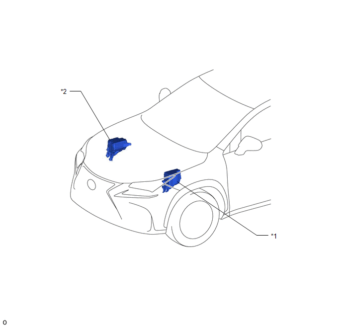
| *1 | NO. 1 ENGINE ROOM RELAY BLOCK AND NO. 1 JUNCTION BLOCK ASSEMBLY - AM2 FUSE - STRG LOCK FUSE | *2 | NO. 2 ENGINE ROOM RELAY BLOCK AND NO. 2 JUNCTION BLOCK ASSEMBLY - IMMOBI FUSE |
ILLUSTRATION
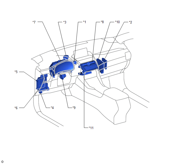
| *1 | POWER SWITCH | *2 | CERTIFICATION ECU (SMART KEY ECU ASSEMBLY) |
| *3 | ID CODE BOX (IMMOBILISER CODE ECU) | *4 | DLC3 |
| *5 | MAIN BODY ECU (MULTIPLEX NETWORK BODY ECU) | *6 | INSTRUMENT PANEL JUNCTION BLOCK ASSEMBLY - IG2 NO.3 FUSE |
| *7 | COMBINATION METER ASSEMBLY | *8 | SECURITY INDICATOR LIGHT (AIR CONDITIONING CONTROL ASSEMBLY) |
| *9 | STEERING LOCK ECU (STEERING LOCK ACTUATOR ASSEMBLY) | *10 | HYBRID VEHICLE CONTROL ECU |
| *11 | DCM (TELEMATICS TRANSCEIVER) (w/ Lexus Enform Remote) | - | - |
READ NEXT:
 System Diagram
SYSTEM DIAGRAM
System Description
SYSTEM DESCRIPTION IMMOBILISER SYSTEM DESCRIPTION (a) The immobiliser system determines whether or not to enable starting of the hybrid control system based on a comparison of the key ID code and the
How To Proceed With Troubleshooting
CAUTION / NOTICE / HINT HINT:
Use this procedure to troubleshoot the immobiliser system.
*: Use the Techstream.
PROCEDURE 1. VEHICLE BROUGHT TO WORKSHOP
NEXT 2.
SEE MORE:
Sound of Portable Player cannot be Heard from Speakers or Sound is Low
PROCEDURE 1. CHECK PORTABLE PLAYER SETTINGS (a) Check the portable player settings. (1) Check that the volume is not set to "0". (2) Check that mute is off. (b) Check that the sound of the portable player can be heard from the speakers. OK: Sound of the portable player can be heard from th
Reassembly
REASSEMBLY CAUTION / NOTICE / HINT HINT:
Use the same procedure for the RH and LH sides.
The procedure listed below is for the LH side.
PROCEDURE 1. INSTALL OUTER MIRROR RETRACTOR LH (a) Install a new frame sub-assembly with the 2 screws. (b) Wind vinyl tape around the harness
© 2016-2026 Copyright www.lexunx.com
