Lexus NX: Door Courtesy Switch Circuit
DESCRIPTION
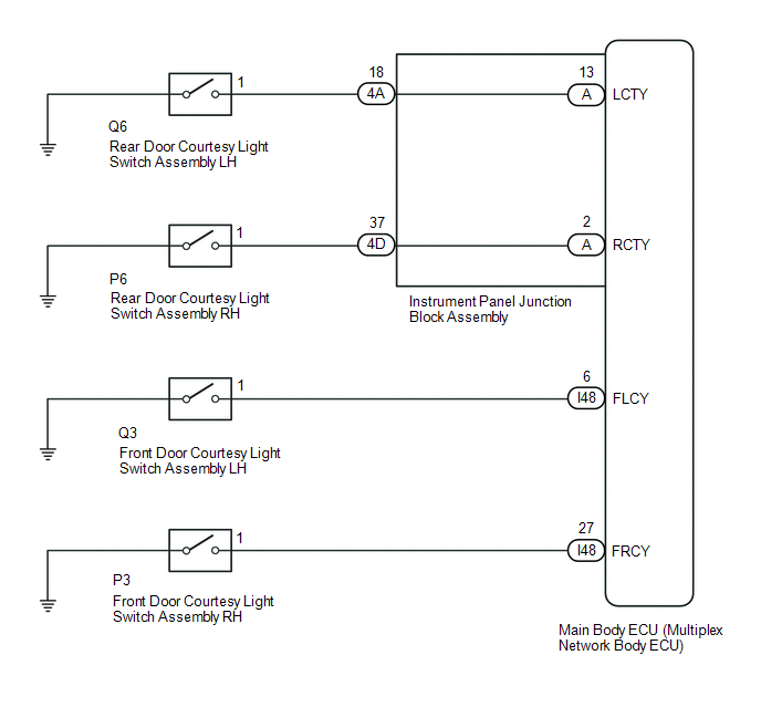
The main body ECU (multiplex network body ECU) receives a door open or closed signal from each door courtesy light switch.
WIRING DIAGRAM
CAUTION / NOTICE / HINT
NOTICE:
- Recognition code registration is necessary when replacing the main body ECU (multiplex network body ECU).
- If the main body ECU (multiplex network body ECU) is replaced, refer to Registration.
PROCEDURE
| 1. | READ VALUE USING TECHSTREAM (DOOR COURTESY SW) |
(a) Using the Techstream, read the Data List.
Click here .gif)
| Tester Display | Measurement Item | Range | Normal Condition | Diagnostic Note |
|---|---|---|---|---|
| RR Door Courtesy SW | Rear door courtesy light switch RH signal | ON or OFF | ON: Rear door RH open OFF: Rear door RH closed | - |
| RL Door Courtesy SW | Rear door courtesy light switch LH signal | ON or OFF | ON: Rear door LH open OFF: Rear door LH closed | - |
| FR Door Courtesy SW | Front door courtesy light switch RH signal | ON or OFF | ON: Front door RH open OFF: Front door RH closed | - |
| FL Door Courtesy SW | Front door courtesy light switch LH signal | ON or OFF | ON: Front door LH open OFF: Front door LH closed | - |
| Tester Display |
|---|
| RR Door Courtesy SW |
| RL Door Courtesy SW |
| FR Door Courtesy SW |
| FL Door Courtesy SW |
OK:
Normal conditions listed above are displayed.
| Result | Proceed to |
|---|---|
| OK | A |
| NG (Front door courtesy light switch assembly RH does not operate) | B |
| NG (Front door courtesy light switch assembly LH does not operate) | C |
| NG (Rear door courtesy light switch assembly RH does not operate) | D |
| NG (Rear door courtesy light switch assembly LH does not operate) | E |
| A | .gif) | PROCEED TO NEXT SUSPECTED AREA SHOWN IN PROBLEM SYMPTOMS TABLE |
| C | | GO TO STEP 4 |
| D | | GO TO STEP 6 |
| E | | GO TO STEP 9 |
|
.gif)
| 2. | INSPECT FRONT DOOR COURTESY LIGHT SWITCH ASSEMBLY RH |
(a) Remove the front door courtesy light switch assembly RH.
Click here
(b) Inspect the front door courtesy light switch assembly RH.
Click here
| NG | | REPLACE FRONT DOOR COURTESY LIGHT SWITCH ASSEMBLY RH |
|
| 3. | CHECK HARNESS AND CONNECTOR (FRONT DOOR COURTESY LIGHT SWITCH ASSEMBLY RH - MAIN BODY ECU [MULTIPLEX NETWORK BODY ECU]) |
(a) Disconnect the P3 front door courtesy light switch assembly RH connector.
(b) Disconnect the I48 main body ECU (multiplex network body ECU) connector.
(c) Measure the resistance according to the value(s) in the table below.
Standard Resistance:
| Tester Connection | Condition | Specified Condition |
|---|---|---|
| P3-1 - I48-27 (FRCY) | Always | Below 1 Ω |
| P3-1 or I48-27 (FRCY) - Body ground | Always | 10 kΩ or higher |
| OK | | REPLACE MAIN BODY ECU (MULTIPLEX NETWORK BODY ECU) |
| NG | | REPAIR OR REPLACE HARNESS OR CONNECTOR |
| 4. | INSPECT FRONT DOOR COURTESY LIGHT SWITCH ASSEMBLY LH |
(a) Remove the front door courtesy light switch assembly LH.
Click here
(b) Inspect the front door courtesy light switch assembly LH.
Click here
| NG | | REPLACE FRONT DOOR COURTESY LIGHT SWITCH ASSEMBLY LH |
|
| 5. | CHECK HARNESS AND CONNECTOR (FRONT DOOR COURTESY LIGHT SWITCH ASSEMBLY LH - MAIN BODY ECU [MULTIPLEX NETWORK BODY ECU]) |
(a) Disconnect the Q3 front door courtesy light switch assembly LH connector.
(b) Disconnect the I48 main body ECU (multiplex network body ECU) connector.
(c) Measure the resistance according to the value(s) in the table below.
Standard Resistance:
| Tester Connection | Condition | Specified Condition |
|---|---|---|
| Q3-1 - I48-6 (FLCY) | Always | Below 1 Ω |
| Q3-1 or I48-6 (FLCY) - Body ground | Always | 10 kΩ or higher |
| OK | | REPLACE MAIN BODY ECU (MULTIPLEX NETWORK BODY ECU) |
| NG | | REPAIR OR REPLACE HARNESS OR CONNECTOR |
| 6. | INSPECT REAR DOOR COURTESY LIGHT SWITCH ASSEMBLY RH |
(a) Remove the rear door courtesy light switch assembly RH.
Click here
(b) Inspect the rear door courtesy light switch assembly RH.
Click here
| NG | | REPLACE REAR DOOR COURTESY LIGHT SWITCH ASSEMBLY RH |
|
| 7. | CHECK HARNESS AND CONNECTOR (REAR DOOR COURTESY LIGHT SWITCH ASSEMBLY RH - INSTRUMENT PANEL JUNCTION BLOCK ASSEMBLY) |
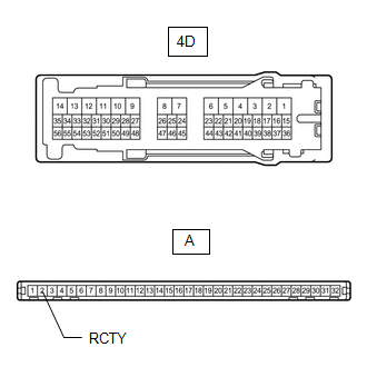
(a) Disconnect the P6 rear door courtesy light switch assembly RH connector.
(b) Disconnect the 4D instrument panel junction block assembly connector.
(c) Measure the resistance according to the value(s) in the table below.
Standard Resistance:
| Tester Connection | Condition | Specified Condition |
|---|---|---|
| P6-1 - 4D-37 | Always | Below 1 Ω |
| P6-1 or 4D-37 - Body ground | Always | 10 kΩ or higher |
| NG | | REPAIR OR REPLACE HARNESS OR CONNECTOR |
|
| 8. | INSPECT INSTRUMENT PANEL JUNCTION BLOCK ASSEMBLY |
| (a) Remove the instrument panel junction block assembly. Click here |
|
(b) Remove the main body ECU (multiplex network body ECU) from the instrument panel junction block assembly.
Click here
(c) Measure the resistance according to the value(s) in the table below.
Standard Resistance:
| Tester Connection | Condition | Specified Condition |
|---|---|---|
| A-2 (RCTY) - 4D-37 | Always | Below 1 Ω |
| OK | | REPLACE MAIN BODY ECU (MULTIPLEX NETWORK BODY ECU) |
| NG | | REPLACE INSTRUMENT PANEL JUNCTION BLOCK ASSEMBLY |
| 9. | INSPECT REAR DOOR COURTESY LIGHT SWITCH ASSEMBLY LH |
(a) Remove the rear door courtesy light switch assembly LH.
Click here
(b) Inspect the rear door courtesy light switch assembly LH.
Click here
| NG | | REPLACE REAR DOOR COURTESY LIGHT SWITCH ASSEMBLY LH |
|
| 10. | CHECK HARNESS AND CONNECTOR (REAR DOOR COURTESY LIGHT SWITCH ASSEMBLY LH - INSTRUMENT PANEL JUNCTION BLOCK ASSEMBLY) |
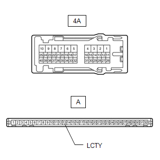
(a) Disconnect the Q6 rear door courtesy light switch assembly LH connector.
(b) Disconnect the 4A instrument panel junction block assembly connector.
(c) Measure the resistance according to the value(s) in the table below.
Standard Resistance:
| Tester Connection | Condition | Specified Condition |
|---|---|---|
| Q6-1 - 4A-18 | Always | Below 1 Ω |
| Q6-1 or 4A-18 - Body ground | Always | 10 kΩ or higher |
| NG | | REPAIR OR REPLACE HARNESS OR CONNECTOR |
|
| 11. | INSPECT INSTRUMENT PANEL JUNCTION BLOCK ASSEMBLY |
| (a) Remove the instrument panel junction block assembly. Click here |
|
(b) Remove the main body ECU (multiplex network body ECU) from the instrument panel junction block assembly.
Click here
(c) Measure the resistance according to the value(s) in the table below.
Standard Resistance:
| Tester Connection | Condition | Specified Condition |
|---|---|---|
| A-13 (LCTY) - 4A-18 | Always | Below 1 Ω |
| OK | | REPLACE MAIN BODY ECU (MULTIPLEX NETWORK BODY ECU) |
| NG | | REPLACE INSTRUMENT PANEL JUNCTION BLOCK ASSEMBLY |
READ NEXT:
 Back Door Courtesy Switch Circuit
DESCRIPTION The main body ECU (multiplex network body ECU) receives a back door open or closed signal from the back door courtesy light switch. WIRING DIAGRAM CAUTION / NOTICE / HINT NOTICE:
Recog
Interior Light Circuit
DESCRIPTION The main body ECU (multiplex network body ECU) controls the map light assembly and spot light assembly. WIRING DIAGRAM CAUTION / NOTICE / HINT NOTICE:
Recognition code registration is
Interior Light Auto Cut Circuit
DESCRIPTION The main body ECU (multiplex network body ECU) controls the DOME CUT relay. WIRING DIAGRAM CAUTION / NOTICE / HINT NOTICE:
Inspect the fuses for circuits related to this system before
SEE MORE:
Data List / Active Test
DATA LIST / ACTIVE TEST READ DATA LIST HINT: Using the Techstream to read the Data List allows the values or states of switches, sensors, actuators and other items to be read without removing any parts. This non-intrusive inspection can be very useful because intermittent conditions or signals may b
System Description
SYSTEM DESCRIPTION
The theft deterrent system can be set/canceled by locking/unlocking the doors performing any of the following operation:
Entry lock/unlock operation
Wireless lock/unlock operation*1
Key linked lock/unlock operation
By opening and closing the doors*2
*1: Using the re
