Lexus NX: Back Door Courtesy Switch Circuit
DESCRIPTION
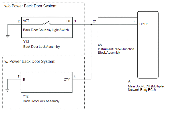
The main body ECU (multiplex network body ECU) receives a back door open or closed signal from the back door courtesy light switch.
WIRING DIAGRAM
CAUTION / NOTICE / HINT
NOTICE:
- Recognition code registration is necessary when replacing the main body ECU (multiplex network body ECU).
- If the main body ECU (multiplex network body ECU) is replaced, refer to Registration.
-
The air conditioning system uses the back door closer system. Inspect the communication function by following How to Proceed with Troubleshooting. Troubleshoot the lighting system after confirming that the communication system is functioning properly.
Click here
.gif)
PROCEDURE
| 1. | READ VALUE USING TECHSTREAM (BACK DOOR COURTESY SW) |
(a) Using the Techstream, read the Data List.
Click here
| Tester Display | Measurement Item | Range | Normal Condition | Diagnostic Note |
|---|---|---|---|---|
| Back Door Courtesy SW | Back door courtesy light switch signal | ON or OFF | ON: Back door open OFF: Back door closed | - |
| Tester Display |
|---|
| Back Door Courtesy SW |
OK:
The display is as specified in the normal condition column.
| OK | .gif) | PROCEED TO NEXT SUSPECTED AREA SHOWN IN PROBLEM SYMPTOMS TABLE |
|
.gif)
| 2. | INSPECT BACK DOOR LOCK ASSEMBLY |
(a) Remove the back door lock assembly.
Click here
(b) Inspect the back door lock assembly.
Click here
| NG | | REPLACE BACK DOOR LOCK ASSEMBLY |
|
| 3. | CHECK HARNESS AND CONNECTOR (BACK DOOR LOCK ASSEMBLY - INSTRUMENT PANEL JUNCTION BLOCK ASSEMBLY AND BODY GROUND) |
(a) w/o Power Back Door System
(1) Disconnect the Y13 back door lock assembly connector.
(2) Disconnect the 4A instrument panel junction block assembly connector.
(3) Measure the resistance according to the value(s) in the table below.
Standard Resistance:
| Tester Connection | Condition | Specified Condition |
|---|---|---|
| Y13-3 (D+) - 4A-21 | Always | Below 1 Ω |
| Y13-2 (ACT-) - Body ground | Always | Below 1 Ω |
| Y13-3 (D+) or 4A-21 - Body ground | Always | 10 kΩ or higher |
(b) w/ Power Back Door System
(1) Disconnect the Y12 back door lock assembly connectors.
(2) Disconnect the 4A instrument panel junction block assembly connector.
(3) Measure the resistance according to the value(s) in the table below.
Standard Resistance:
| Tester Connection | Condition | Specified Condition |
|---|---|---|
| Y12-8 (CYT) - 4A-21 | Always | Below 1 Ω |
| Y12-7 (E) - Body ground | Always | Below 1 Ω |
| Y12-8 (CTY) or 4A-21 - Body ground | Always | 10 kΩ or higher |
| NG | | REPAIR OR REPLACE HARNESS OR CONNECTOR |
|
| 4. | INSPECT INSTRUMENT PANEL JUNCTION BLOCK ASSEMBLY |
| (a) Remove the instrument panel junction block assembly. Click here |
|
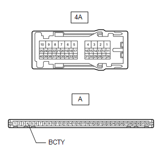
(b) Remove the main body ECU (multiplex network body ECU) from the instrument panel junction block assembly.
Click here
(c) Measure the resistance according to the value(s) in the table below.
Standard Resistance:
| Tester Connection | Condition | Specified Condition |
|---|---|---|
| A-4 (BCTY) - 4A-21 | Always | Below 1 Ω |
| OK | | REPLACE MAIN BODY ECU (MULTIPLEX NETWORK BODY ECU) |
| NG | | REPLACE INSTRUMENT PANEL JUNCTION BLOCK ASSEMBLY |
READ NEXT:
 Interior Light Circuit
DESCRIPTION The main body ECU (multiplex network body ECU) controls the map light assembly and spot light assembly. WIRING DIAGRAM CAUTION / NOTICE / HINT NOTICE:
Recognition code registration is
Interior Light Auto Cut Circuit
DESCRIPTION The main body ECU (multiplex network body ECU) controls the DOME CUT relay. WIRING DIAGRAM CAUTION / NOTICE / HINT NOTICE:
Inspect the fuses for circuits related to this system before
Interior Light Switch Signal Circuit
DESCRIPTION The main body ECU (multiplex network body ECU) detects the condition of the door switch and front dome light switch. WIRING DIAGRAM Click here CAUTION / NOTICE / HINT NOTICE:
Recognit
SEE MORE:
Operation Check
OPERATION CHECK HINT: The blind spot monitor beam axis confirmation is performed to confirm whether the sensor's beam axis is correct, and perform adjustment of the beam axis by using reflector. BLIND SPOT MONITOR BEAM AXIS CONFIRMATION (a) When performing the blind spot monitor beam axis confirmati
Seat Heater for Rear Left Seat does not Operate
DESCRIPTION When the refreshing seat switch is operated, the air conditioning amplifier assembly receives the signal via the LIN communication line, and operates the seat heater for the corresponding rear seat. WIRING DIAGRAM CAUTION / NOTICE / HINT NOTICE:
If the auxiliary battery voltage is l
