Lexus NX: Ignition Switch Run Position Circuit High (P2532-772)
DESCRIPTION
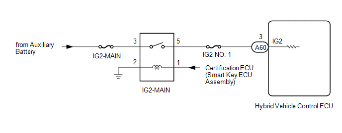
The hybrid vehicle control ECU monitors the IGSW signals sent from the smart key ECU assembly (certification ECU) and detects a malfunction.
HINT:
If DTC P2532-772 is stored, the vehicle will turn off (READY off).
| DTC No. | Detection Item | DTC Detection Condition | Trouble Area | MIL | Warning Indicate |
|---|---|---|---|---|---|
| P2532-772 | Ignition Switch Run Position Circuit High | When communication is lost from ECU that has IG1 circuit power supply and power is supplied to IG2 terminal (1 trip detection logic) |
| Does not come on | Master Warning Light: Comes on |
WIRING DIAGRAM
CAUTION / NOTICE / HINT
HINT:
After the repair, clear the DTCs and perform the following procedure to check that DTCs are not output.
- Turn the power switch on (IG) and wait for 15 seconds or more.
- Turn the power switch off and wait for 30 seconds or more.
PROCEDURE
| 1. | CHECK DTC OUTPUT (HYBRID CONTROL) |
(a) Connect the Techstream to the DLC3.
(b) Turn the power switch on (IG).
(c) Enter the following menus: Powertrain / Hybrid Control / Trouble Codes.
(d) Check for DTCs.
Powertrain > Hybrid Control > Trouble Codes(e) Turn the power switch off.
| DTCs except P2532-772 are output. | .gif) | GO TO STEP 6 |
|
.gif)
| 2. | READ VALUE USING TECHSTREAM (CAN BUS CHECK) |
(a) Connect the Techstream to the DLC3.
(b) Turn the power switch on (IG).
(c) Enter the following menus: System Select / CAN Bus Check.
CAN Bus Check| Result | Proceed to |
|---|---|
| All of the ECUs and sensors that are currently connected to the CAN communication system are displayed. | A |
| None of the ECUs and sensors that are currently connected to the CAN communication system are displayed, or some of them are not displayed. | B |
(d) Turn the power switch off.
| B | | GO TO CAN COMMUNICATION SYSTEM |
|
| 3. | CHECK HARNESS AND CONNECTOR (+B SHORT) |
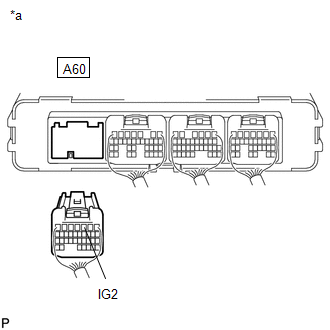
| (a) Disconnect the A60 hybrid vehicle control ECU connector. |
|
(b) Measure the voltage according to the value(s) in the table below.
Standard Voltage:
| Tester Connection | Condition | Specified Condition |
|---|---|---|
| A60-3 (IG2) - Body ground | Power switch off | 1 V or less |
(c) Reconnect the A60 hybrid vehicle control ECU connector.
| OK | | REPLACE HYBRID VEHICLE CONTROL ECU |
|
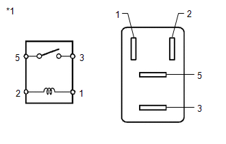
| 4. | INSPECT RELAY (IG2-MAIN) |
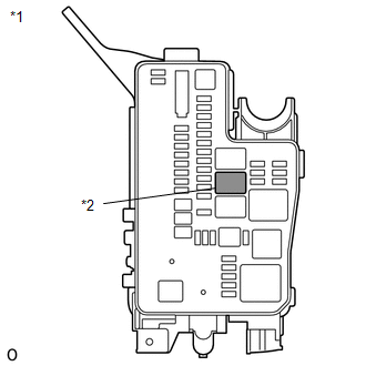
| (a) Remove the IG2-MAIN relay from the No. 1 engine room relay block. |
|
| (b) Measure the resistance according to the value(s) in the table below. Standard Resistance:
|
|
(c) Install the IG2-MAIN relay.
| NG | | REPLACE RELAY (IG2-MAIN) |
|
| 5. | CHECK HARNESS AND CONNECTOR (HYBRID VEHICLE CONTROL ECU - IG2-MAIN RELAY) |
(a) Disconnect the A60 hybrid vehicle control ECU connector.
| (b) Remove the IG2-MAIN relay from the No. 1 engine room relay block. |
|
| (c) Measure the voltage according to the value(s) in the table below. Standard Voltage:
|
|
(d) Install the IG2-MAIN relay.
(e) Reconnect the A60 hybrid vehicle control ECU connector.
| NG | | REPAIR OR REPLACE HARNESS OR CONNECTOR |
|
| 6. | CHECK FOR INTERMITTENT PROBLEMS |
(a) Check for intermittent problems.
Click here .gif)
(1) Check the connection and terminal contact pressure of the connectors and wire harnesses between the hybrid vehicle control ECU and the No. 1 engine room relay block.
(2) When the power switch is on (READY), jiggle the connectors and wire harnesses between the hybrid vehicle control ECU and the No. 1 engine room relay block.
| Problem symptom does not recur. | | REPLACE HYBRID VEHICLE CONTROL ECU |
| Problem symptom recurs. | | REPAIR OR REPLACE MALFUNCTIONING PARTS, COMPONENT AND AREA |
READ NEXT:
 Battery Control System (P3000-388)
DESCRIPTION The hybrid vehicle control ECU alerts the driver and performs fail-safe control based on error signals received from the battery voltage sensor. This DTC is stored when the SOC (state of c
High Voltage Power Resource (P3004-131)
DTC SUMMARY MALFUNCTION DESCRIPTION The hybrid vehicle control ECU monitors the high-voltage wiring between the HV battery and inverter with converter assembly and detects an open circuit malfunction.
High Voltage Power Resource (P3004-800,P3004-801)
DTC SUMMARY MALFUNCTION DESCRIPTION The hybrid vehicle control ECU monitors the high-voltage wiring between the HV battery and inverter with converter assembly and detects a short circuit malfunction
SEE MORE:
Operation Check
OPERATION CHECK CHECK POWER DOOR LOCK OPERATION NOTICE: The operation check below is based on the non-customized initial condition of the vehicle. (a) Check basic functions. (1) Check that all doors lock when the lock side of the door control switch is pressed. (2) Check that all doors unlock when t
ICS Detection Area Adjustment Incomplete (C1AF0)
DESCRIPTION When ICS detection area adjustment is incomplete, the clearance warning ECU assembly stores DTC C1AF0. DTC No. Detection Item DTC Detection Condition Trouble Area C1AF0 ICS Detection Area Adjustment Incomplete ICS detection area adjustment incomplete
Intelligent cle
