Lexus NX: Inspection
INSPECTION
CAUTION / NOTICE / HINT
HINT:
- Use the same procedure for the RH and LH sides.
- The procedure listed below is for the LH side.
PROCEDURE
1. INSPECT REAR STABILIZER LINK ASSEMBLY LH
NOTICE:
Since the rear stabilizer link, rear stabilizer cushions and lock nut are not reusable, new parts must be installed.
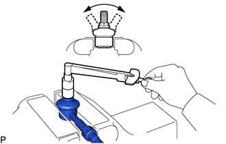
(a) Inspect the turning torque of the ball joint.
(1) Secure the rear stabilizer link assembly in a vise using aluminum plates.
(2) Install the nut to the rear stabilizer link assembly stud.
(3) Move the stud back and forth several times. Using a torque wrench, turn the nut continuously at a rate of 3 to 5 seconds per turn and take the torque reading on the 5th turn.
Standard turning torque:
0.05 to 1.96 N*m (0.5 to 20 kgf*cm, 0.4 to 17 in.*lbf)
If the turning torque is not within the specified range, replace the rear stabilizer link assembly with a new one.
(b) Inspect the dust cover.
(1) Check that the dust cover is not cracked and that there is no grease on it.
READ NEXT:
 Installation
INSTALLATION PROCEDURE 1. INSTALL REAR STABILIZER BUSHING (a) Install the 2 rear stabilizer bushings to the rear stabilizer bar on the outside of the bush stoppers as shown in the illustration. NOTIC
Components
COMPONENTS ILLUSTRATION *1 DECK FLOOR BOX LH *2 NO. 3 DECK BOARD SUB-ASSEMBLY *3 REAR DECK FLOOR BOX *4 NEGATIVE AUXILIARY BATTERY TERMINAL N*m (kgf*cm, ft.*lbf): Specified
SEE MORE:
Interior Light Auto Cut Circuit
DESCRIPTION The main body ECU (multiplex network body ECU) controls the DOME CUT relay. WIRING DIAGRAM CAUTION / NOTICE / HINT NOTICE:
Inspect the fuses for circuits related to this system before performing the following procedure.
Recognition code registration is necessary when replacing the
Components
COMPONENTS ILLUSTRATION *A w/ AVS - - *1 REAR AXLE CARRIER SUB-ASSEMBLY LH *2 REAR HEIGHT CONTROL SENSOR SUB-ASSEMBLY LH *3 REAR NO. 1 SHOCK ABSORBER BRACKET LH *4 REAR NO. 1 SUSPENSION ARM ASSEMBLY LH *5 REAR NO. 2 SUSPENSION ARM ASSEMBLY LH *6 REAR STABILIZE
