Lexus NX: Components
COMPONENTS
ILLUSTRATION
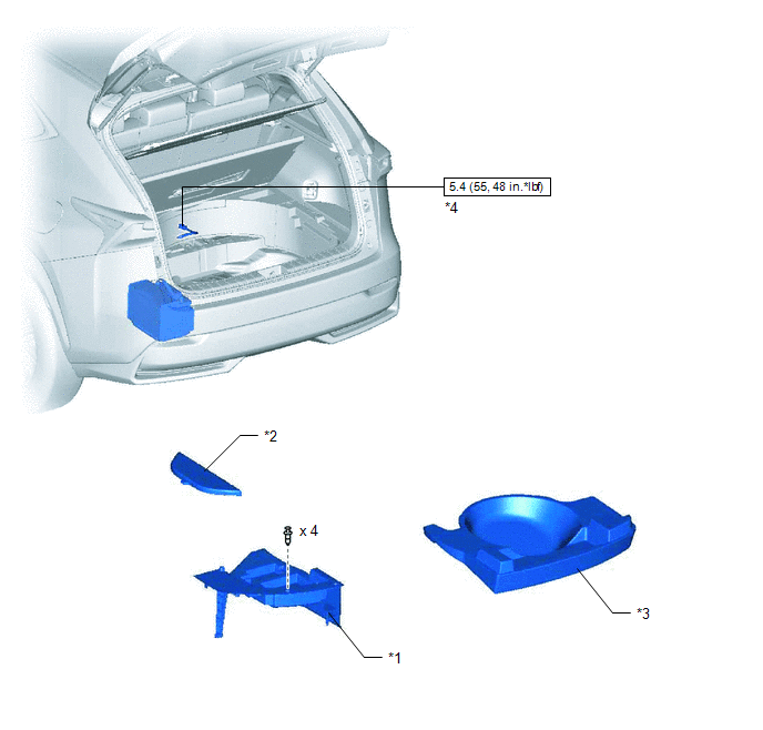
| *1 | DECK FLOOR BOX LH | *2 | NO. 3 DECK BOARD SUB-ASSEMBLY |
| *3 | REAR DECK FLOOR BOX | *4 | NEGATIVE AUXILIARY BATTERY TERMINAL |
.png) | N*m (kgf*cm, ft.*lbf): Specified torque | - | - |
ILLUSTRATION
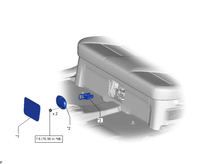
| *1 | BATTERY SERVICE HOLE COVER | *2 | HYBRID BATTERY SERVICE PLUG COVER |
| *3 | SERVICE PLUG GRIP | - | - |
| | N*m (kgf*cm, ft.*lbf): Specified torque | - | - |
ILLUSTRATION
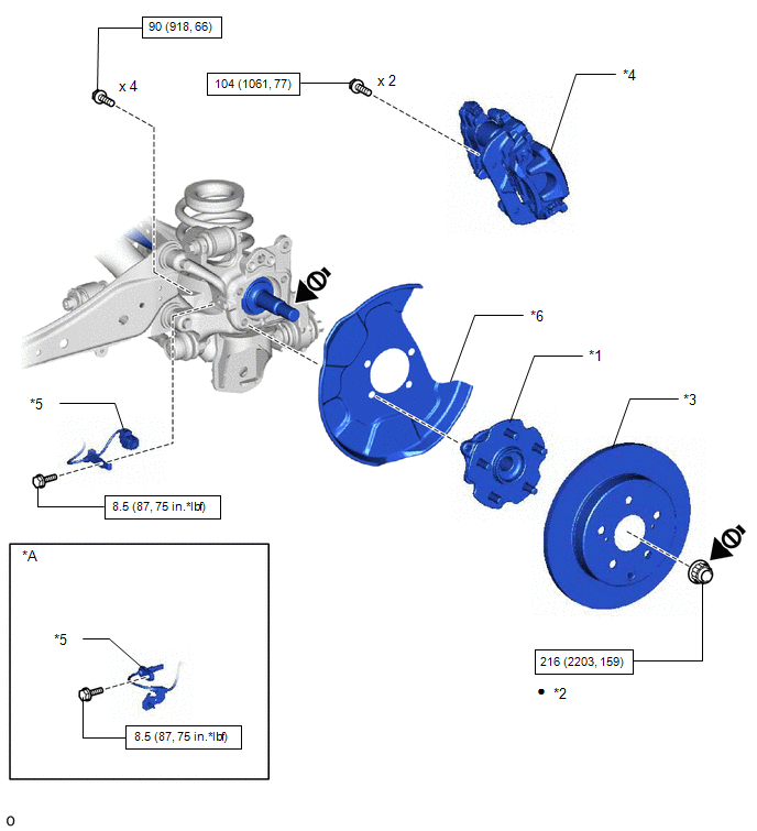
| *A | w/ AVS | - | - |
| *1 | REAR AXLE HUB AND BEARING ASSEMBLY LH | *2 | REAR AXLE SHAFT NUT LH |
| *3 | REAR DISC | *4 | REAR DISC BRAKE CALIPER ASSEMBLY LH |
| *5 | REAR SPEED SENSOR LH | *6 | REAR DISC BRAKE DUST COVER SUB-ASSEMBLY LH |
| | N*m (kgf*cm, ft.*lbf): Specified torque | ● | Non-reusable part |
.png) | Do not apply lubricants to the threaded parts | - | - |
ILLUSTRATION
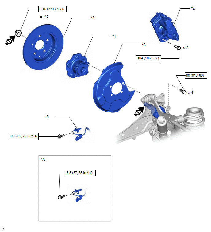
| *A | w/ AVS | - | - |
| *1 | REAR AXLE HUB AND BEARING ASSEMBLY RH | *2 | REAR AXLE SHAFT NUT RH |
| *3 | REAR DISC | *4 | REAR DISC BRAKE CALIPER ASSEMBLY RH |
| *5 | REAR SPEED SENSOR RH | *6 | REAR DISC BRAKE DUST COVER SUB-ASSEMBLY RH |
| | N*m (kgf*cm, ft.*lbf): Specified torquev | ● | Non-reusable part |
| | Do not apply lubricants to the threaded parts | - | - |
ILLUSTRATION
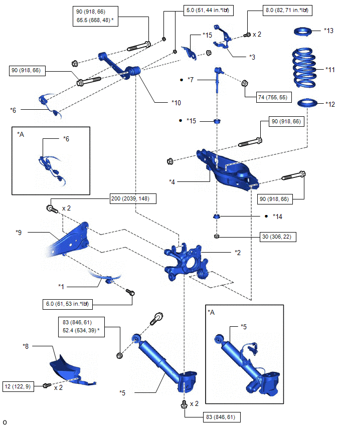
| *A | w/ AVS | - | - |
| *1 | PARKING BRAKE WIRE ASSEMBLY NO.1 | *2 | REAR AXLE CARRIER SUB-ASSEMBLY LH |
| *3 | REAR HEIGHT CONTROL SENSOR SUB-ASSEMBLY LH | *4 | REAR NO. 2 SUSPENSION ARM ASSEMBLY LH |
| *5 | REAR SHOCK ABSORBER ASSEMBLY LH | *6 | REAR SPEED SENSOR LH |
| *7 | REAR STABILIZER LINK ASSEMBLY LH | *8 | REAR SUSPENSION ARM COVER LH |
| *9 | REAR TRAILING ARM ASSEMBLY LH | *10 | REAR UPPER CONTROL ARM ASSEMBLY LH |
| *11 | REAR COIL SPRING LH | *12 | REAR LOWER COIL SPRING INSULATOR LH |
| *13 | REAR UPPER COIL SPRING INSULATOR LH | *14 | REAR STABILIZER CUSHION |
| *15 | PARKING BRAKE WIRE BRACKET | - | - |
| | N*m (kgf*cm, ft.*lbf): Specified torque | ● | Non-reusable part |
| * | For use with ball joint lock nut wrench | - | - |
ILLUSTRATION
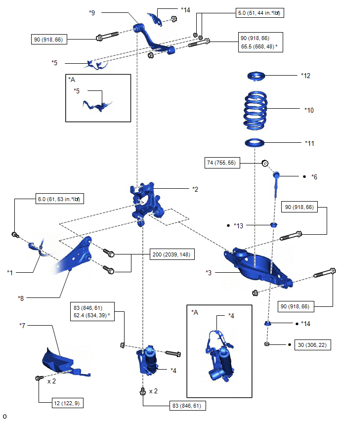
| *A | w/ AVS | - | - |
| *1 | PARKING BRAKE WIRE ASSEMBLY NO.1 | *2 | REAR AXLE CARRIER SUB-ASSEMBLY RH |
| *3 | REAR NO. 2 SUSPENSION ARM ASSEMBLY RH | *4 | REAR SHOCK ABSORBER ASSEMBLY RH |
| *5 | REAR SPEED SENSOR RH | *6 | REAR STABILIZER LINK ASSEMBLY RH |
| *7 | REAR SUSPENSION ARM COVER RH | *8 | REAR TRAILING ARM ASSEMBLY RH |
| *9 | REAR UPPER CONTROL ARM ASSEMBLY RH | *10 | REAR COIL SPRING RH |
| *11 | REAR LOWER COIL SPRING INSULATOR RH | *12 | REAR UPPER COIL SPRING INSULATOR RH |
| *13 | REAR STABILIZER CUSHION | *14 | PARKING BRAKE WIRE BRACKET |
| | N*m (kgf*cm, ft.*lbf): Specified torque | ● | Non-reusable part |
| * | For use with ball joint lock nut wrench | - | - |
ILLUSTRATION
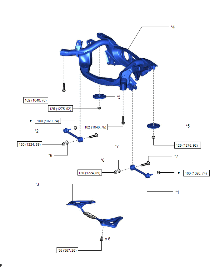
| *1 | REAR NO. 1 SUSPENSION ARM ASSEMBLY LH | *2 | REAR NO. 1 SUSPENSION ARM ASSEMBLY RH |
| *3 | REAR SUSPENSION BRACE SUB-ASSEMBLY | *4 | REAR SUSPENSION MEMBER SUB-ASSEMBLY |
| *5 | REAR UPPER REAR SUSPENSION MEMBER CUSHION | *6 | NO. 2 CAMBER ADJUST CAM |
| *7 | REAR SUSPENSION TOE ADJUST CAM SUB-ASSEMBLY | - | - |
| | N*m (kgf*cm, ft.*lbf): Specified torque | ● | Non-reusable part |
ILLUSTRATION
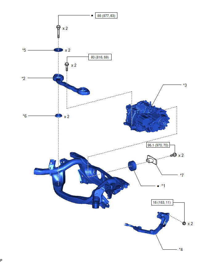
| *1 | DIFFERENTIAL MOUNT CUSHION | *2 | FRONT DIFFERENTIAL SUPPORT ASSEMBLY |
| *3 | REAR TRACTION WITH TRANSAXLE MOTOR ASSEMBLY | *4 | NO. 2 FRAME WIRE |
| *5 | UPPER DIFFERENTIAL MOUNT STOPPER | *6 | LOWER DIFFERENTIAL MOUNT STOPPER |
| *7 | DIFFERENTIAL DYNAMIC DAMPER | - | - |
| | N*m (kgf*cm, ft.*lbf): Specified torque | ● | Non-reusable part |
ILLUSTRATION
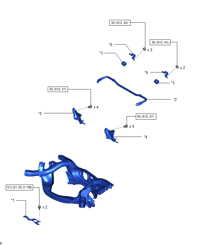
| *1 | CABLE SUPPORT BRACKET | *2 | REAR STABILIZER BAR |
| *3 | REAR STABILIZER BUSHING | *4 | REAR STABILIZER SUPPORT BRACKET LH |
| *5 | REAR STABILIZER SUPPORT BRACKET RH | *6 | REAR NO. 1 STABILIZER BRACKET |
| | N*m (kgf*cm, ft.*lbf): Specified torque | - | - |
READ NEXT:
 Removal
REMOVAL CAUTION / NOTICE / HINT NOTICE:
When the brake pedal is first depressed after replacing the brake pads or pushing back the disc brake piston, DTC C1214 may be output. As there is no malfunc
Installation
INSTALLATION PROCEDURE 1. INSTALL CABLE SUPPORT BRACKET (a) Install the cable support bracket to the rear suspension member sub-assembly with the 2 bolts. Torque: 6.0 N·m {61 kgf·cm, 53 in·lbf} 2.
SEE MORE:
Removal
REMOVAL PROCEDURE 1. REMOVE TIMING CHAIN COVER ASSEMBLY Click here 2. REMOVE EXHAUST MANIFOLD CONVERTER SUB-ASSEMBLY Click here 3. REMOVE THROTTLE WITH MOTOR BODY ASSEMBLY Click here 4. REMOVE WATER BY-PASS PIPE Click here 5. REMOVE EGR COOLER ASSEMBLY Click here 6. REMOVE EGR VALVE ASSE
Calibration
CALIBRATION NOTICE: When any of the following parts have been replaced, perform adjustment shown in the following table. If not, the intuitive parking assist system may not operate correctly. ADJUST INTUITIVE PARKING ASSIST SYSTEM (a) The necessary procedures (adjustment, calibration, initialization
