Lexus NX: Adjustment
ADJUSTMENT
CAUTION / NOTICE / HINT
HINT:
- Use the same procedure for the RH and LH sides.
- The procedure listed below is for the LH side.
PROCEDURE
1. PREPARE VEHICLE FOR FOG LIGHT AIM ADJUSTMENT
(a) Prepare the vehicle:
- Ensure that there is no damage or deformation to the vehicle body around the fog lights.
- Fill the fuel tank.
- Make sure that the oil is filled to the specified level.
- Make sure that the engine coolant is filled to the specified level.
- Inflate the tires to the appropriate pressure.
- Unload the trunk and vehicle, ensuring that the spare tire, tools and jack are in their original positions.
- Have a person of average weight (68 kg, 150 lb) sit in the driver seat.
2. PREPARE FOR FOG LIGHT AIMING
(a) Prepare the vehicle:
-
Place the vehicle in a location that is dark enough to clearly observe the cutoff line. The cutoff line is a distinct line, below which light from the fog lights can be observed and above which it cannot.
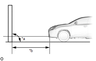
*a
90°
*b
7.62 m or 3 m
- Place the vehicle at a 90° angle to the wall.
-
Create a 7.62 m (25.0 ft.) distance between the vehicle (base point marks of fog light) and the wall.
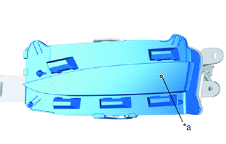
*a
Base point Mark
- Make sure that the vehicle is on a level surface.
- Position the front wheels straight ahead.
- Bounce the vehicle up and down to settle the suspension.
NOTICE:
A distance of 7.62 m (25.0 ft.) between the vehicle (base point marks of fog light) and the wall is necessary for proper aim adjustment. If sufficient space is not available, secure a distance of exactly 3 m (9.84 ft.) to allow for checking and adjustment of fog light aim. (The size of the target zone will change with the distance, so follow the instructions in the illustration.)
(b) Prepare a piece of thick white paper (approximately 2 m (6.56 ft.) (height) x 4 m (13.1 ft.) (width)) to use as a screen.
(c) Draw a vertical line down the center of the screen (V line).
(d) Set the screen as shown in the illustration.
HINT:
- Stand the screen perpendicular to the ground.
- Align the V line on the screen with the center of the vehicle.
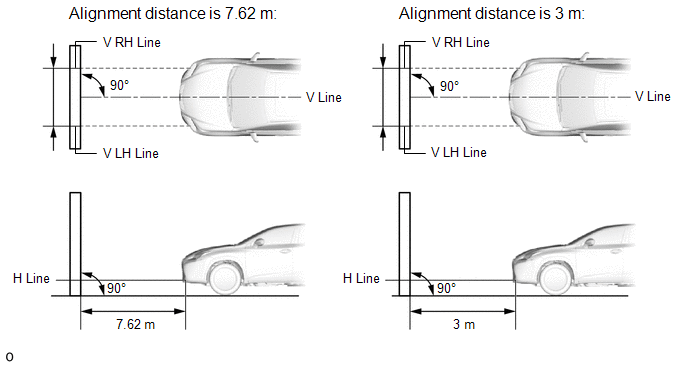
| (e) Draw base lines (H, V LH, and V RH lines) on the screen as shown in the illustration. HINT: Mark the aiming marks on the screen. (1) H Line (Fog light height): Draw a horizontal line across the screen so that it passes through the base point marks. The H line should be at the same height as the base point marks of the fog lights. (2) V LH Line, V RH Line (Base point mark position of left-hand (LH) and right-hand (RH) fog lights): Draw 2 vertical lines so that they intersect the H line at each base point mark (aligned with the base point marks of the fog lights). |
|
.png)
3. INSPECT FOG LIGHT AIMING
(a) Cover the fog light on the opposite side to prevent light from the fog light that is not being inspected from affecting the fog light aiming inspection.
(b) Start the engine.
(c) Turn on the fog lights and check if the upper edge of the hot zone for each fog light matches the upper edge as shown in the illustration.
HINT:
-
If the alignment distance is 7.62 m (25.0 ft.):
The upper edge of the hot zone for the fog light should be 115 mm (4.51 in.) below the H line.
-
If the alignment distance is 3 m (9.84 ft.):
The upper edge of the hot zone for the fog light should be 46 mm (1.78 in.) below the H line.
.png)
4. ADJUST FOG LIGHT AIMING
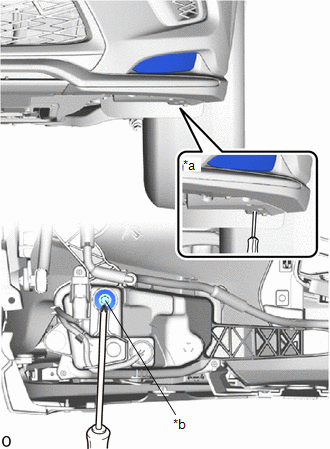
| (a) Adjust the aim vertically: Adjust the aim of each fog light to the specified range by turning each aiming screw with a screwdriver insert from the service hole. NOTICE: The final turn of the aiming screw should be made in the clockwise direction. If the screw is tightened excessively, loosen it and then retighten it, so that the final turn of the screw is in the clockwise direction. HINT: If it is not possible to correctly adjust the fog light aim, check the fog light assembly, fog light unit installation. |
|
READ NEXT:
 Reassembly
REASSEMBLY CAUTION / NOTICE / HINT NOTICE:
Handle components indoors as much as possible to prevent foreign matter from entering and adhering to fog light assembly components.
Do not reuse parts
Installation
INSTALLATION CAUTION / NOTICE / HINT HINT:
Use the same procedure for the RH and LH sides.
The procedure described below is for the LH side.
PROCEDURE 1. INSTALL FOG LIGHT ASSEMBLY LH (a) Inst
Front Side Marker Light Bulb(for Single Beam Headlight)
ReplacementREPLACEMENT CAUTION / NOTICE / HINT HINT:
Use the same procedure for the RH and LH sides.
The procedure listed below is for the LH side.
PROCEDURE 1. REMOVE FRONT SIDE MARKER LIGHT
SEE MORE:
Open or Short in Steering Angle Sensor +B (C1625)
DESCRIPTION This DTC is stored if the rear television camera assembly receives a signal via CAN communication from the steering sensor that indicates a power supply problem. DTC No. Detection Item DTC Detection Condition Trouble Area C1625 Open or Short in Steering Angle Sensor +B O
Front Camera Feedback Malfunction (C1681)
DESCRIPTION This DTC is stored if the parking assist ECU judges as a result of its self check that a synchronization problem is occurring in the image signal sent from the front television camera assembly to the parking assist ECU. DTC No. Detection Item DTC Detection Condition Trouble Area
