Lexus NX: Over Current Detected in Driver Side Camera (C1687)
DESCRIPTION
This DTC is stored if the parking assist ECU judges as a result of its self check that a synchronization problem is occurring in the image signal sent from the driver side television camera assembly to the parking assist ECU.
| DTC No. | Detection Item | DTC Detection Condition | Trouble Area |
|---|---|---|---|
| C1687 | Over Current Detected in Driver Side Camera | Side camera current malfunction |
|
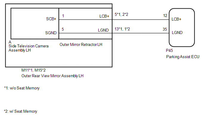
WIRING DIAGRAM
CAUTION / NOTICE / HINT
NOTICE:
-
When "!" mark is displayed on the multi-display assembly after the cable is disconnected from the negative (-) auxiliary battery terminal, correct the steering angle neutral point.
Click here
.gif)
-
Depending on the parts that are replaced or operations that are performed during vehicle inspection or maintenance, calibration of other systems as well as the panoramic view monitor system may be needed.
Click here
PROCEDURE
| 1. | CHECK FOR DTC |
(a) Clear the DTCs.
Click here
(b) Check for DTCs.
Click here
OK:
DTC C1687 is not output.
| Result | Proceed to |
|---|---|
| OK | A |
| NG | B |
| A | .gif) | USE SIMULATION METHOD TO CHECK |
|
.gif)
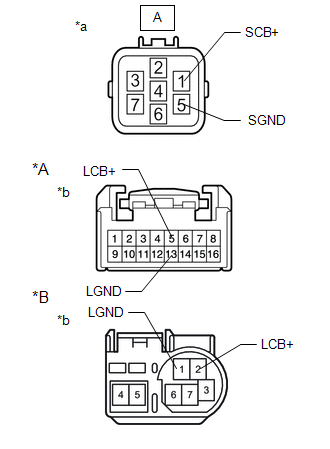
| 2. | CHECK HARNESS AND CONNECTOR (PARKING ASSIST ECU - OUTER REAR VIEW MIRROR ASSEMBLY LH) |
(a) Disconnect the P45 parking assist ECU connector.
(b) Disconnect the M11*1 or M15*2 outer rear view mirror assembly LH connector.
- *1: w/o Seat Memory
- *2: w/ Seat Memory
(c) Measure the resistance according to the value(s) in the table below.
Standard Resistance:
w/o Seat Memory| Tester Connection | Condition | Specified Condition |
|---|---|---|
| P45-12 (LCB+) - M11-5 (LCB+) | Always | Below 1 Ω |
| P45-35 (LGND) - M11-13 (LGND) | Always | Below 1 Ω |
| P45-12 (LCB+) or M11-5 (LCB+) - Body ground | Always | 10 kΩ or higher |
| P45-35 (LGND) or M11-13 (LGND) - Body ground | Always | 10 kΩ or higher |
| Tester Connection | Condition | Specified Condition |
|---|---|---|
| P45-12 (LCB+) - M15-2 (LCB+) | Always | Below 1 Ω |
| P45-35 (LGND) - M15-1 (LGND) | Always | Below 1 Ω |
| P45-12 (LCB+) or M15-2 (LCB+) - Body ground | Always | 10 kΩ or higher |
| P45-35 (LGND) or M15-1 (LGND) - Body ground | Always | 10 kΩ or higher |
| NG | | REPAIR OR REPLACE HARNESS OR CONNECTOR |
|
| 3. | CHECK PARKING ASSIST ECU |
| (a) Disconnect the outer rear view mirror assembly LH connector |
|
.png)
(b) Measure the resistance according to the value(s) in the table below.
Standard Resistance:
| Tester Connection | Condition | Specified Condition |
|---|---|---|
| P45-35 (LGND) - Body ground | Always | Below 1 Ω |
(c) Measure the voltage according to the value(s) in the table below.
Standard Voltage:
| Tester Connection | Switch Condition | Specified Condition |
|---|---|---|
| P45-12 (LCB+) - P45-35 (LGND) | Power switch on (IG) | 5.5 to 7.05 V |
| P45-12 (LCB+) - P45-35 (LGND) | Power switch off | Below 1 V |
| NG | | REPLACE PARKING ASSIST ECU |
|
| 4. | INSPECT OUTER MIRROR RETRACTOR LH |
| (a) Remove the outer mirror retractor LH. Click here |
|
(b) Measure the resistance according to the value(s) in the table below.
Standard Resistance:
w/o Seat Memory| Tester Connection | Condition | Specified Condition |
|---|---|---|
| A-1 (SCB+) - 5 (LCB+) | Always | Below 1 Ω |
| A-5 (SGND) - 13 (LGND) | Always | Below 1 Ω |
| A-1 (SCB+) or 5 (LCB+) - Body ground | Always | 10 kΩ or higher |
| A-5 (SGND) or 13 (LGND) - Body ground | Always | 10 kΩ or higher |
| Tester Connection | Condition | Specified Condition |
|---|---|---|
| A-1 (SCB+) - 2 (LCB+) | Always | Below 1 Ω |
| A-5 (SGND) - 1 (LGND) | Always | Below 1 Ω |
| A-1 (SCB+) or 2 (LCB+) - Body ground | Always | 10 kΩ or higher |
| A-5 (SGND) or 1 (LGND) - Body ground | Always | 10 kΩ or higher |
| NG | | REPLACE OUTER MIRROR RETRACTOR LH |
|
| 5. | CHECK SIDE TELEVISION CAMERA ASSEMBLY LH |
(a) Replace the side television camera assembly LH with a new or normally functioning one.
Click here
|
| 6. | CHECK FOR DTC |
(a) Clear the DTCs.
Click here
(b) Check for DTCs.
Click here
OK:
DTC C1687 is not output.
| OK | | END (SIDE TELEVISION CAMERA ASSEMBLY LH IS DEFECTIVE) |
| NG | | REPLACE PARKING ASSIST ECU |
READ NEXT:
 Vehicle Information Unmatched (C168D)
DESCRIPTION This DTC is stored if the parking assist ECU judges as a result of its self check that the vehicle information received via CAN communication and the vehicle information stored in the park
Steering Angle Initialization Incomplete (C1694)
DESCRIPTION This DTC is stored when the parking assist ECU judges that the maximum steering angle has not been memorized (steering angle setting is incomplete). DTC No. Detection Item DTC Detec
Camera Position Adjustment Incomplete (C1697)
DESCRIPTION This DTC is stored when the parking assist ECU judges that the camera initial setting has not been memorized (camera view adjustment is incomplete). DTC No. Detection Item DTC Detec
SEE MORE:
Remote Touch
Remote Touch
The Remote Touch can be used to
operate the navigation/multimedia
system display Owners of models
equipped with a navigation system
should refer to the "NAVIGATION
AND MULTIMEDIA SYSTEM
OWNER'S MANUAL".
Remote Touch operation
■ Switches
10.3-inch display model
"MAP" bu
Dcm(telematics Transceiver)
ComponentsCOMPONENTS ILLUSTRATION *1 DECK FLOOR BOX LH *2 NO. 3 DECK BOARD SUB-ASSEMBLY *3 REAR DECK FLOOR BOX *4 NEGATIVE AUXILIARY BATTERY TERMINAL N*m (kgf*cm, ft.*lbf): Specified torque - - ILLUSTRATION *A for 8 Inch *B for 10.3 Inch *1 AIR COND
