Lexus NX: Inspection
INSPECTION
PROCEDURE
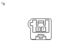
1. INSPECT FRONT NO. 2 SPEAKER ASSEMBLY
| (a) Measure the resistance according to the value(s) in the table below. Standard Resistance: for 8 Speakers
If the result is not as specified, replace the front No. 2 speaker assembly. |
|

(b) When there is a malfunction such as noise from a speaker or no sound at all, replace the speaker with a new one and check that the malfunction disappears.
OK:
Malfunction disappears.
HINT:
- Connect the connectors to the front No. 2 speaker assemblies.
- When there is a possibility that either the right or left front No. 2 speaker assembly is defective, inspect by interchanging the right one with the left one.
- Perform the inspection above on both the LH and RH side.
2. INSPECT FRONT NO. 3 SPEAKER ASSEMBLY
| (a) Measure the resistance according to the value(s) in the table below. Standard Resistance: for 10 Speakers
If the result is not as specified, replace the front No. 3 speaker assembly. |
|
READ NEXT:
 Installation
INSTALLATION CAUTION / NOTICE / HINT HINT:
Use the same procedure for the RH and LH sides.
The procedure listed below is for the LH side.
PROCEDURE 1. INSTALL FRONT NO. 3 SPEAKER ASSEMBLY NOTI
On-vehicle Inspection
ON-VEHICLE INSPECTION PROCEDURE 1. INSPECT RADIO SETTING CONDENSER (a) With the radio setting condenser installed, check that there is no looseness or other abnormalities. (b) Measure the resistanc
SEE MORE:
A/C Inverter Low Voltage Power Resource System Malfunction (B1477)
DESCRIPTION The compressor with motor assembly monitors the inverter control power voltage in the circuit. The hybrid vehicle control ECU stops the compressor control and stores this DTC when the monitored voltage is outside the specified range. This DTC will be stored as a history DTC. Compressor c
Data List / Active Test
DATA LIST / ACTIVE TEST DATA LIST NOTICE: In the table below, the values listed under "Normal Condition" are reference values. Do not depend solely on these reference values when deciding whether a part is faulty or not. HINT: Using the Techstream to read the Data List allows the values or states of
