Lexus NX: Installation
INSTALLATION
PROCEDURE
1. INSTALL POWER STEERING ECU ASSEMBLY
(a) Install a new electric power steering motor shaft damper to the power steering ECU assembly.
(b) Install a new electric power steering motor shaft spacer to the power steering ECU assembly.
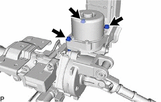
| (c) Temporarily install the power steering ECU assembly to the electric power steering column sub-assembly with the 3 bolts. NOTICE: Do not tighten the bolts until the heads contact the surface of the power steering ECU assembly. Leave a small amount of clearance so that the power steering ECU assembly can be centered in a later procedure. |
|
(d) Remove the No. 2 steering intermediate shaft assembly from the electric power steering column sub-assembly.
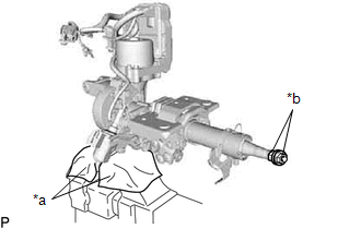
| (e) Secure the electric power steering column sub-assembly in a vise between aluminum plates or pieces of cloth as shown in the illustration. NOTICE:
|
|
(f) Install the 2 nuts to the electric power steering column sub-assembly.
HINT:
The nuts to use are the steering wheel set nut or equivalents.
| Steering wheel set nut part No. | Thread diameter | Thread pitch |
|---|---|---|
| 90179-12071 | 12 mm (0.4724 in.) | 1.25 mm (0.0492 in.) |
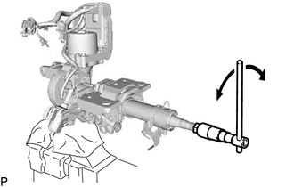
| (g) Turn the steering main shaft by 180° to the left and right at a speed of 1 turn per second. Repeat these movements 2 to 3 times to center the power steering ECU assembly. |
|
(h) Tighten the 3 bolts.
Torque:
18.5 N·m {189 kgf·cm, 14 ft·lbf}
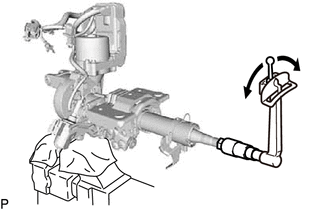
| (i) Check the turning torque of the steering main shaft. Standard preload: 0.9 to 1.5 N*m (10 to 15 kgf*cm, 8 to 13 in.*lbf) NOTICE: Make sure that the shaft turns smoothly. HINT: If the result is not as specified, center the power steering ECU assembly again. |
|
(j) Install the No. 2 steering intermediate shaft assembly to the electric power steering column sub-assembly.
Torque:
35.3 N·m {360 kgf·cm, 26 ft·lbf}
(k) Connect the 2 connector clamps of a new ECU wire harness sub-assembly to the harness bracket.
(l) Connect the 3 connectors to the power steering ECU assembly.
(m) Install the 2 cable ties and heat resistant tape.
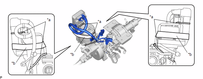
| *a | Cable Tie | *b | Heat Resistant Tape |
NOTICE:
As heat from the power steering motor assembly may generate smoke, use heat resistant tape (resistant to 100°C (212°F) or higher).
(n) Install a new power steering ECU protector to the power steering ECU assembly.
2. INSTALL ELECTRIC POWER STEERING COLUMN SUB-ASSEMBLY
Click here .gif)
3. PERFORM TORQUE SENSOR ZERO POINT CALIBRATION
Click here
4. PERFORM ASSIST MAP WRITING
Click here
READ NEXT:
 Precaution
PRECAUTION HANDLING PRECAUTIONS FOR SRS AIRBAG SYSTEM (a) This vehicle is equipped with a Supplemental Restraint System (SRS). Failure to carry out service operations in the correct sequence could cau
Parts Location
PARTS LOCATION ILLUSTRATION *1 POWER STEERING ECU ASSEMBLY *2 ELECTRIC POWER STEERING COLUMN SUB-ASSEMBLY - POWER STEERING MOTOR ASSEMBLY - MOTOR ROTATION ANGLE SENSOR - TORQUE SENSOR - ECU
SEE MORE:
Precaution
PRECAUTION PRECAUTION FOR DISCONNECTING CABLE FROM NEGATIVE AUXILIARY BATTERY TERMINAL NOTICE: After the power switch is turned off, the radio receiver assembly records various types of memory and settings. As a result, after turning the power switch off, make sure to wait at least 6 minutes before
Operation Check
OPERATION CHECK INSPECT INDICATOR/WARNING LIGHT (a) Check the following indicators and warning lights. Indicator/Warning Light Switch Condition Specified Condition
*1: w/ Pre-collision System
*2: w/ Automatic High Beam System Brake warning light Power switch off → on (IG) Comes
