Lexus NX: Inspection
INSPECTION
PROCEDURE
1. INSPECT INTEGRATION CONTROL AND PANEL ASSEMBLY
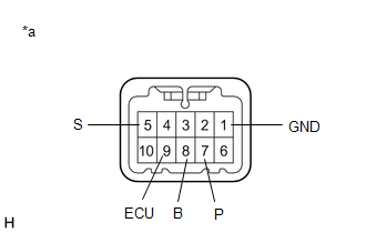
| (a) Measure the resistance according to the value(s) in the table below. Standard Resistance:
If the result is not as specified, replace the integration control and panel assembly. |
|
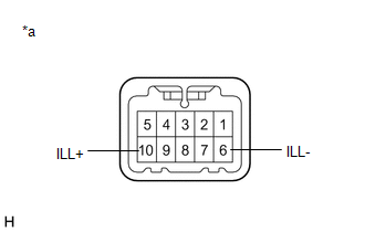
| (b) Apply battery voltage between the terminals of the switch, and check the illumination condition of the integration control and panel assembly. Standard:
If the result is not as specified, replace the integration control and panel assembly. |
|
READ NEXT:
 Installation
INSTALLATION PROCEDURE 1. INSTALL INTEGRATION CONTROL AND PANEL ASSEMBLY (a) Install the integration control and panel assembly to the rear upper console panel sub-assembly with the 2 screws. HINT:
On-vehicle Inspection
ON-VEHICLE INSPECTION PROCEDURE 1. REMOVE NO. 1 ENGINE UNDER COVER ASSEMBLY Click here 2. INSPECT HYBRID TRANSAXLE FLUID (a) Using a 10 mm hexagon socket wrench, remove the filler plug and gask
SEE MORE:
Generator Inverter Performance (P0A7A-325,P0A7A-810)
DTC SUMMARY MALFUNCTION DESCRIPTION These DTCs indicate that a large current flowed in the inverter for the generator. The cause of this malfunction may be one of the following: Internal inverter malfunction
Internal circuit malfunction in the inverter for the generator
Malfunction in the senso
Short in P Squib (Dual Stage - 2nd Step) Circuit (B1815-B1818)
DESCRIPTION The front passenger side squib 2nd step circuit consists of the airbag ECU assembly and instrument panel passenger airbag. The circuit instructs the SRS to deploy when deployment conditions are met. These DTCs are stored when a malfunction is detected in the front passenger side squib 2n
