Lexus NX: On-vehicle Inspection
ON-VEHICLE INSPECTION
PROCEDURE
1. REMOVE NO. 1 ENGINE UNDER COVER ASSEMBLY
Click here .gif)
2. INSPECT HYBRID TRANSAXLE FLUID
| (a) Using a 10 mm hexagon socket wrench, remove the filler plug and gasket from the hybrid vehicle transaxle assembly. |
|
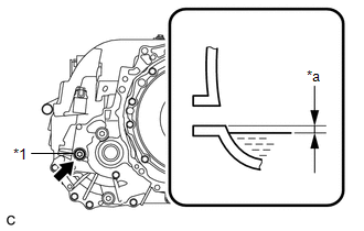
(b) Check that the hybrid transaxle fluid level is between 0 to 5 mm (0 to 0.196 in.) from the bottom lip of the filler plug opening. (If the hybrid transaxle fluid level is too low, return to the Add Hybrid Transaxle Fluid procedure.)
NOTICE:
- Stop the vehicle on a level surface.
- Be sure to directly check that the hybrid transaxle fluid level is within the specified range.
- Insufficient or excessive amounts of hybrid transaxle fluid may damage the hybrid vehicle transaxle assembly.
- If the hybrid transaxle fluid was replaced or hybrid transaxle fluid was added, make sure to recheck the hybrid transaxle fluid level after driving the vehicle.
(c) Check for leaks if the hybrid transaxle fluid level is low. (If there are no hybrid transaxle fluid leaks but the amount of the hybrid transaxle fluid is insufficient, add hybrid transaxle fluid.)
Click here
(d) Using a 10 mm hexagon socket wrench, install the filler plug with a new gasket to the hybrid vehicle transaxle assembly.
Torque:
39.2 N·m {400 kgf·cm, 29 ft·lbf}
3. INSTALL NO. 1 ENGINE UNDER COVER ASSEMBLY
Click here
READ NEXT:
 Replacement
REPLACEMENT PROCEDURE 1. REPLACE HYBRID TRANSAXLE FLUID (a) Be sure that the vehicle remains level and lift the vehicle. [*1] (b) Remove the No. 1 engine under cover assembly. Click here (c) Usin
Adjustment
ADJUSTMENT PROCEDURE 1. REMOVE NO. 1 ENGINE UNDER COVER ASSEMBLY Click here 2. DRAIN HYBRID TRANSAXLE FLUID (a) Using a 10 mm hexagon socket wrench, remove the filler plug and gasket from the hyb
Hybrid Transaxle Oil Seal
ComponentsCOMPONENTS ILLUSTRATION *1 FRONT DRIVE SHAFT OIL SEAL LH *2 FRONT DRIVE SHAFT OIL SEAL RH ● Non-reusable part MP grease ATF WS - - ReplacementREPLACEME
SEE MORE:
Terminals Of Ecu
TERMINALS OF ECU CLEARANCE WARNING ECU ASSEMBLY (a) Disconnect the I20 clearance warning ECU assembly connector. (b) Measure the voltage and resistance on the wire harness side connector according to the value(s) in the table below. Terminal No. (Symbol) Wiring Color Terminal Description C
Installation
INSTALLATION PROCEDURE 1. INSTALL INSTRUMENT PANEL PASSENGER AIRBAG ASSEMBLY (a) Attach the 3 hooks on the side of the airbag door facing the front of the vehicle and set the instrument panel passenger airbag assembly onto the airbag door. *A Front of the Vehicle *B Rear of the Vehicle
