Lexus NX: Installation
INSTALLATION
PROCEDURE
1. INSTALL INTEGRATION CONTROL AND PANEL ASSEMBLY
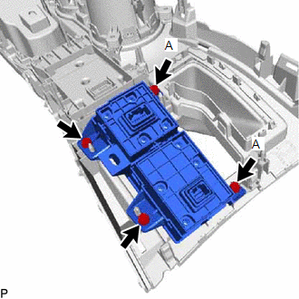
| (a) Install the integration control and panel assembly to the rear upper console panel sub-assembly with the 2 screws. HINT: The locations labeled A in the illustration are tightened together with the shift position indicator. |
|
2. INSTALL SHIFT POSITION INDICATOR
Click here .gif)
3. INSTALL UPPER REAR CONSOLE PANEL SUB-ASSEMBLY
Click here
4. INSTALL SHIFT LEVER KNOB SUB-ASSEMBLY
Click here
5. INSTALL CENTER INSTRUMENT CLUSTER FINISH PANEL ASSEMBLY
Click here
6. INSTALL NO. 2 INSTRUMENT PANEL SAFETY PAD SUB-ASSEMBLY
Click here
7. INSTALL NO. 1 SWITCH HOLE BASE
Click here
8. INSTALL LOWER NO. 1 INSTRUMENT PANEL FINISH PANEL
Click here
9. INSTALL NO. 1 INSTRUMENT PANEL UNDER COVER SUB-ASSEMBLY
Click here
10. INSTALL NO. 1 INSTRUMENT PANEL SAFETY PAD SUB-ASSEMBLY
Click here
11. INSTALL INSTRUMENT SIDE PANEL LH
Click here
12. INSTALL INSTRUMENT SIDE PANEL RH
Click here
13. INSTALL UPPER NO. 2 CONSOLE PANEL GARNISH
Click here
14. INSTALL UPPER NO. 1 CONSOLE PANEL GARNISH
Click here
15. INSTALL UPPER REAR CONSOLE PANEL
Click here
16. INSTALL CONSOLE ARMREST ASSEMBLY
Click here
17. INSTALL MULTI-DISPLAY ASSEMBLY WITH BRACKET
Click here
18. INSTALL INSTRUMENT PANEL FINISH PLATE
READ NEXT:
 On-vehicle Inspection
ON-VEHICLE INSPECTION PROCEDURE 1. REMOVE NO. 1 ENGINE UNDER COVER ASSEMBLY Click here 2. INSPECT HYBRID TRANSAXLE FLUID (a) Using a 10 mm hexagon socket wrench, remove the filler plug and gask
Replacement
REPLACEMENT PROCEDURE 1. REPLACE HYBRID TRANSAXLE FLUID (a) Be sure that the vehicle remains level and lift the vehicle. [*1] (b) Remove the No. 1 engine under cover assembly. Click here (c) Usin
SEE MORE:
Disassembly
DISASSEMBLY CAUTION / NOTICE / HINT HINT:
Use the same procedure for the RH and LH sides.
The procedure listed below is for the LH side.
PROCEDURE 1. REMOVE OUTER MIRROR LH Click here 2. REMOVE SIDE TURN SIGNAL LIGHT ASSEMBLY LH Click here 3. REMOVE SIDE TELEVISION CAMERA ASSEMBLY LH (w/
Back Door Courtesy Switch Circuit
DESCRIPTION The fold seat control ECU receives the switch operation signal, driving condition signal and back door open/close signal from the back door lock assembly. The fold seat control ECU actives the rear seat according to these signals. WIRING DIAGRAM PROCEDURE 1. CHECK BACK DOOR LOCK A
