Lexus NX: Inspection
INSPECTION
PROCEDURE
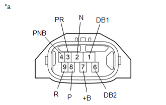
1. INSPECT SHIFT LEVER POSITION SENSOR
| (a) Measure the resistance according to the value(s) in the table below. Standard Resistance:
If the result is not as specified, replace the shift lever position sensor. |
|
READ NEXT:
 Adjustment
ADJUSTMENT PROCEDURE 1. INSPECT SHIFT LEVER POSITION SENSOR POSITION (a) Apply the parking brake. (b) Lock the wheels with chocks to secure the vehicle. (c) Turn the power switch on (READY). (d) Move
Installation
INSTALLATION PROCEDURE 1. INSTALL SHIFT LEVER POSITION SENSOR (a) Install the shift lever position sensor to the manual valve shaft. (b) Temporarily install the 2 bolts. (c) Install the lock plate and
SEE MORE:
Short in Side Squib (LH) Circuit (B1825-B1828)
DESCRIPTION The front side squib LH circuit consists of the airbag ECU assembly and front seat airbag assembly LH. The circuit instructs the SRS to deploy when deployment conditions are met. These DTCs are stored when a malfunction is detected in the front side squib LH circuit. DTC No. Detecti
Fail-safe Chart
FAIL-SAFE CHART FAIL-SAFE FUNCTION (a) When communication fails in any of the CAN bus wires (communication wires), a fail-safe function(s) operates. The fail-safe function that is specified for each system operates to prevent those systems from malfunctioning. (b) Effects on each system when communi
