Lexus NX: Removal
REMOVAL
CAUTION / NOTICE / HINT
HINT:
- Use the same procedure for the RH and LH sides.
- The procedure listed below is for the LH side.
PROCEDURE
1. REMOVE SIDE MUDGUARD SUB-ASSEMBLY LH
HINT:
When removing the side mudguard sub-assembly LH, if the No. 3 moulding tape (double-sided tape) is difficult to remove, heat the adhesive of the side mudguard sub-assembly LH using a heat light.
Standard:
| Item | Temperature |
|---|---|
| Side Mudguard Sub-assembly LH | 40 to 60°C (104 to 140°F) |
NOTICE:
Do not heat the side mudguard sub-assembly LH excessively.
| (a) Remove the screw. |
|
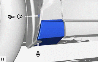
(b) Remove the clip.
(c) Using a clip remover, remove the grommet.
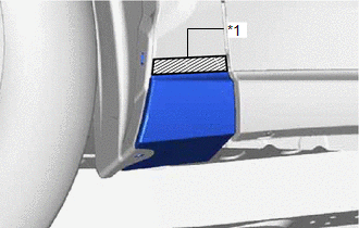
| (d) Put protective tape around the side mudguard sub-assembly LH. |
|
(e) Detach the 2 clips and remove the side mudguard sub-assembly LH.
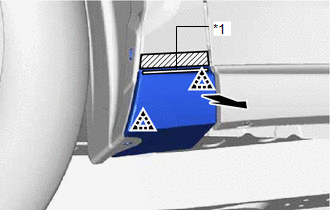
| *1 | No. 3 Moulding Tape (Double-sided Tape) |
.png) | Direction to Pull |
READ NEXT:
 Disassembly
DISASSEMBLY CAUTION / NOTICE / HINT HINT:
Use the same procedure for the RH and LH sides.
The procedure listed below is for the LH side.
PROCEDURE 1. REMOVE NO. 3 MOULDING TAPE (a) Remove the
Reassembly
REASSEMBLY CAUTION / NOTICE / HINT HINT:
Use the same procedure for the RH and LH sides.
The procedure listed below is for the LH side.
PROCEDURE 1. INSTALL NO. 3 MOULDING TAPE (a) Clean the N
Installation
INSTALLATION CAUTION / NOTICE / HINT HINT:
Use the same procedure for the RH and LH sides.
The procedure listed below is for the LH side.
PROCEDURE 1. INSTALL SIDE MUDGUARD SUB-ASSEMBLY LH HIN
SEE MORE:
Installation
INSTALLATION CAUTION / NOTICE / HINT HINT:
Use the same procedure for RHD and LHD vehicles.
The procedure listed below is for LHD vehicles.
PROCEDURE 1. INSTALL COOLER THERMISTOR (ROOM TEMPERATURE SENSOR) (a) Connect the aspirator hose. (b) Connect the connector. (c) Attach the 2 claws to in
Odo/Trip Switch Malfunction
DESCRIPTION The ODO/TRIP display of the combination meter changes each time the trip switch is pressed. WIRING DIAGRAM CAUTION / NOTICE / HINT NOTICE: When replacing the combination meter assembly, make sure to replace it with a new one. PROCEDURE 1. READ VALUE USING TECHSTREAM (ODO/TRIP CHAN
© 2016-2026 Copyright www.lexunx.com
