Lexus NX: Installation
INSTALLATION
PROCEDURE
1. INSTALL SERVICE PLUG GRIP
CAUTION:
Wear insulating gloves.
NOTICE:
Before connecting the service plug, check that no parts and tools remain and that the high voltage terminals and connectors are connected securely.
(a) Wear insulated gloves and install the service plug grip in the order shown in the illustration.
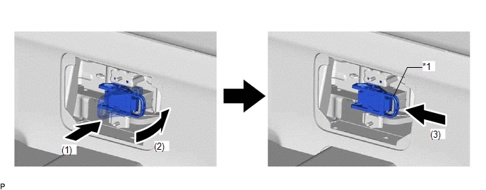
| *1 | Service Plug Grip Lever | - | - |
(1) Insert the service plug grip straight.
(2) Push down the lever 90°.
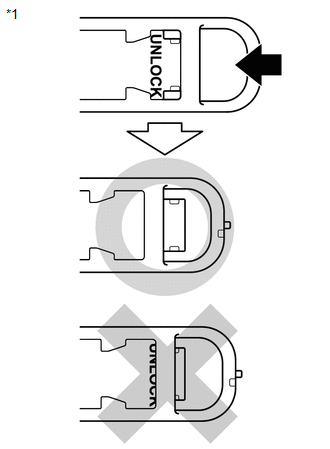
| (3) Slide the lever until it clicks to indicate that it is locked. NOTICE: Slide firmly to the left until the UNLOCK indication is hidden. |
|
(b) Rotate the handle of the service plug grip 90° toward the battery and slide it in the direction shown by the arrow until a "click" sound is heard.
2. INSTALL HYBRID BATTERY SERVICE PLUG COVER
CAUTION:
Wear insulated gloves and use insulated tools.
| (a) Using an insulated tool, install the hybrid battery service plug cover with the 2 nuts. Torque: 7.5 N·m {76 kgf·cm, 66 in·lbf} |
|
.png)
3. INSTALL BATTERY SERVICE HOLE COVER
.png)
(a) Attach the 4 claws and install the battery service hole cover.
HINT:
Attach the upper 2 claws and then pull them up to remove.
4. CONNECT CABLE TO NEGATIVE AUXILIARY BATTERY TERMINAL
(a) Connect the cable to the negative (-) auxiliary battery terminal and tighten the nut.
Torque:
5.4 N·m {55 kgf·cm, 48 in·lbf}
5. INITIALIZATION AFTER RECONECTING AUXILIARY BATTERY TERMINAL
Click here .gif)
HINT:
When disconnecting and reconnecting the auxiliary battery, there is an automatic learning function that completes learning when the respective system is used.
Click here
6. INSTALL DECK FLOOR BOX LH
Click here
7. INSTALL REAR DECK FLOOR BOX
Click here
8. INSTALL NO. 3 DECK BOARD SUB-ASSEMBLY
Click here
READ NEXT:
 Sub Radiator
RemovalREMOVAL PROCEDURE 1. REMOVE NO. 1 ENGINE UNDER COVER ASSEMBLY Click here 2. DRAIN COOLANT (for Inverter Coolant) Click here 3. REMOVE UPPER RADIATOR SUPPORT SUB-ASSEMBLY Click here 4.
Components
COMPONENTS ILLUSTRATION *1 HV WATER PUMP BRACKET SUB-ASSEMBLY *2 NO. 1 ENGINE UNDER COVER ASSEMBLY *3 NO. 2 INVERTER COOLING HOSE ASSEMBLY *4 WATER PUMP WITH MOTOR *5 NO. 2 I
SEE MORE:
On-vehicle Inspection
ON-VEHICLE INSPECTION CAUTION / NOTICE / HINT NOTICE: DTCs may be stored during the inspection procedure. Be sure to clear the DTCs and check that no DTCs are output after the inspection is finished. PROCEDURE 1. INSPECT PRESSURE SENSOR (a) Check auxiliary battery voltage. Standard voltage: 11 to 1
Customize Parameters
CUSTOMIZE PARAMETERS CUSTOMIZE POWER DOOR LOCK CONTROL SYSTEM HINT: The following items can be customized. NOTICE:
When the customer requests a change in a function, first make sure that the function can be customized.
Be sure to make a note of the current settings before customizing.
When tr
