Lexus NX: Sub Radiator
Removal
REMOVAL
PROCEDURE
1. REMOVE NO. 1 ENGINE UNDER COVER ASSEMBLY
Click here .gif)
2. DRAIN COOLANT (for Inverter Coolant)
Click here
3. REMOVE UPPER RADIATOR SUPPORT SUB-ASSEMBLY
Click here
4. REMOVE NO. 2 FAN SHROUD
Click here
5. REMOVE RADIATOR ASSEMBLY (for Inverter Coolant)
| (a) Slide the hose clamp, and disconnect the No. 5 inverter cooling hose and No. 2 inverter cooling hose assembly from the radiator assembly (for inverter coolant). NOTICE:
HINT: Prepare a drain pan or cloth in case the coolant leaks. |
|
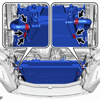
(b) Remove the 4 bolts and radiator assembly (for inverter coolant) from the cooler condenser assembly.
Installation
INSTALLATION
PROCEDURE
1. INSTALL RADIATOR ASSEMBLY (for Inverter Coolant)
| (a) Install the radiator assembly (for inverter coolant) to the cooler condenser assembly with the 4 bolts. Torque: 9.0 N·m {92 kgf·cm, 80 in·lbf} |
|
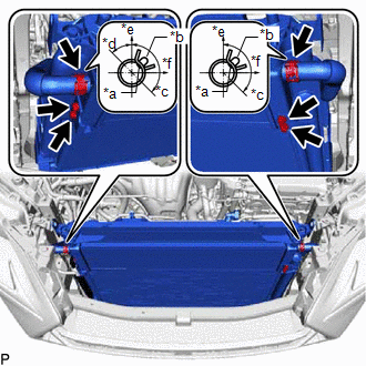
(b) Referring to the illustration, connect the No. 5 inverter cooling hose, No. 2 inverter cooling hose assembly and clamp to the radiator assembly (for inverter coolant), and secure with the hose clamp.
NOTICE:
- Until immediately before connecting the water hose, plug the water hose and pipe with vinyl tape, etc. to prevent foreign matter from entering the cooling path.
- Insert the water hose up to the tank surface of the radiator assembly (for inverter coolant).
- Align the matchmark on the water hose with the positioning rib on the radiator assembly (for inverter coolant).
2. INSTALL NO. 2 FAN SHROUD
Click here .gif)
3. INSTALL UPPER RADIATOR SUPPORT SUB-ASSEMBLY
Click here
4. ADD COOLANT (for Inverter Coolant)
Click here
5. INSPECT FOR COOLANT LEAK (for Inverter Coolant)
Click here
6. INSTALL NO. 1 ENGINE UNDER COVER ASSEMBLY
Click here
READ NEXT:
 Components
COMPONENTS ILLUSTRATION *1 HV WATER PUMP BRACKET SUB-ASSEMBLY *2 NO. 1 ENGINE UNDER COVER ASSEMBLY *3 NO. 2 INVERTER COOLING HOSE ASSEMBLY *4 WATER PUMP WITH MOTOR *5 NO. 2 I
Removal
REMOVAL PROCEDURE 1. REMOVE NO. 1 ENGINE UNDER COVER ASSEMBLY Click here 2. DRAIN COOLANT (for Inverter Coolant) Click here 3. REMOVE UPPER RADIATOR SUPPORT SUB-ASSEMBLY Click here 4. DISCONNE
SEE MORE:
Oxygen Sensor Heater Control Circuit Low (Bank 1 Sensor 2) (P0037,P0038,P0141,P102D)
DESCRIPTION Refer to DTC P0136. Click here HINT: When any of these DTCs are stored, the ECM enters fail-safe mode. The ECM turns off the heated oxygen sensor heater in fail-safe mode. Fail-safe mode continues until the power switch is turned off. DTC No. Detection Item DTC Detection Condi
If the 12-volt battery is discharged
The following procedures may be
used to start the hybrid system if the
vehicle's 12-volt battery is discharged.
You can also call your Lexus dealer
or a qualified repair shop.
Restarting the hybrid system
If you have a set of jumper (or booster)
cables and a second vehicle with a 12-
volt
