Lexus NX: Installation
INSTALLATION
PROCEDURE
1. INSTALL STEREO COMPONENT EQUALIZER ASSEMBLY
(a) Install the stereo component equalizer assembly with 2 nuts.
2. INSTALL STEREO COMPONENT EQUALIZER ASSEMBLY WITH BRACKET
| (a) Connect all the connectors and temporarily install the stereo component equalizer assembly by attaching the 2 guides of the stereo component equalizer assembly with bracket to the instrument panel. |
|
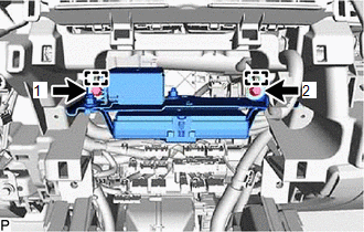
(b) Install the stereo component equalizer assembly with bracket with the 2 bolts.
HINT:
Tighten the screws in the order shown in the illustration.
3. INSTALL RADIO RECEIVER ASSEMBLY WITH BRACKET
Click here .gif)
4. CONNECT CABLE TO NEGATIVE AUXILIARY BATTERY TERMINAL
5. INITIALIZATION AFTER RECONNECTING AUXILIARY BATTERY TERMINAL
Click here
HINT:
When disconnecting and reconnecting the auxiliary battery, there is an automatic learning function that completes learning when the respective system is used.
Click here
6. CHECK SRS WARNING LIGHT
Click here
7. INSTALL DECK FLOOR BOX LH
Click here
8. INSTALL REAR DECK FLOOR BOX
Click here
9. INSTALL NO. 3 DECK BOARD SUB-ASSEMBLY
Click here
10. INSTALL DECK BOARD ASSEMBLY
Click here
READ NEXT:
 Asc Speaker
ComponentsCOMPONENTS ILLUSTRATION *1 NO. 1 SPEAKER ASSEMBLY WITH BOX - - RemovalREMOVAL PROCEDURE 1. REMOVE CONSOLE BOX ASSEMBLY Click here 2. REMOVE NO. 1 SPEAKER ASSEMBLY WITH BOX
Components
COMPONENTS ILLUSTRATION *1 CONSOLE ARMREST ASSEMBLY *2 INSTRUMENT SIDE PANEL LH *3 LOWER NO. 1 INSTRUMENT PANEL FINISH PANEL *4 NO. 1 INSTRUMENT PANEL SAFETY PAD SUB-ASSEMBLY *
SEE MORE:
Cooling System
DESCRIPTION The cause of the malfunction may be the cooling system. Check whether the grille is blocked, whether coolant is leaking, the HV radiator fan operating condition and whether coolant has frozen. Related Parts Check Area Inspection Step Grille blockage, coolant amount, coolant ho
Removal
REMOVAL CAUTION / NOTICE / HINT NOTICE: When replacing the combination meter assembly, make sure to replace it with a new one. PROCEDURE 1. DISABLE AUTOAWAY/RETURN FUNCTION (for Power Tilt and Power Telescopic Steering Column) (a) Disable the autoaway/return function by changing the customize parame
