Lexus NX: Asc Speaker
Components
COMPONENTS
ILLUSTRATION
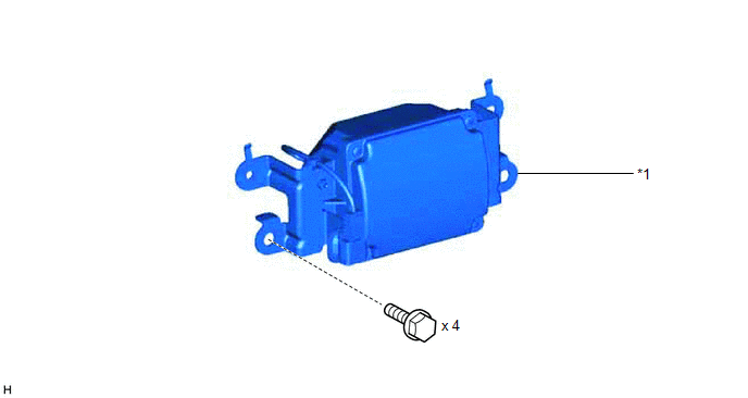
| *1 | NO. 1 SPEAKER ASSEMBLY WITH BOX | - | - |
Removal
REMOVAL
PROCEDURE
1. REMOVE CONSOLE BOX ASSEMBLY
Click here .gif)
2. REMOVE NO. 1 SPEAKER ASSEMBLY WITH BOX
| (a) Remove the 4 bolts and disconnect the connector. |
|
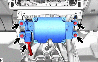
(b) Detach the 2 claws used to temporarily fix the part in place and remove the No. 1 speaker assembly with box.
Inspection
INSPECTION
PROCEDURE
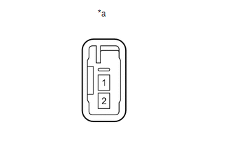
1. INSPECT NO. 1 SPEAKER ASSEMBLY W/ BOX
| (a) Measure the resistance according to the value(s) in the table below. Standard Resistance:
If the result is not as specified, replace the No. 1 speaker assembly w/ box. |
|
Installation
INSTALLATION
PROCEDURE
1. INSTALL NO. 1 SPEAKER ASSEMBLY WITH BOX
| (a) Temporarily install the No. 1 speaker assembly with box by attaching the 2 claws of the No. 1 speaker assembly with box to the instrument panel. |
|
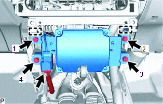
(b) Install the No. 1 speaker assembly with box with the 4 bolts in the order shown in the illustration.
(c) Connect the connector.
2. INSTALL CONSOLE BOX ASSEMBLY
Click here .gif)
READ NEXT:
 Components
COMPONENTS ILLUSTRATION *1 CONSOLE ARMREST ASSEMBLY *2 INSTRUMENT SIDE PANEL LH *3 LOWER NO. 1 INSTRUMENT PANEL FINISH PANEL *4 NO. 1 INSTRUMENT PANEL SAFETY PAD SUB-ASSEMBLY *
Removal
REMOVAL PROCEDURE 1. REMOVE CONSOLE ARMREST ASSEMBLY Click here 2. REMOVE UPPER REAR CONSOLE PANEL Click here 3. REMOVE UPPER NO. 2 CONSOLE PANEL GARNISH Click here 4. REMOVE INSTRUMENT SI
SEE MORE:
Check Bus 2 Lines for Short Circuit
DESCRIPTION There may be a short circuit between the CAN main bus wire and/or CAN branch wire when the resistance between terminals 18 (CA4H) and 17 (CA4L) of the central gateway ECU (network gateway ECU) is below 54 Ω. Symptom Trouble Area
*1: w/ Headup Display
*2: w/ ASC System *3: for T
Data List / Active Test
DATA LIST / ACTIVE TEST READ DATA LIST NOTICE: In the table below, the values listed under "Normal Condition" are reference values. Do not depend solely on these reference values when deciding whether a part is faulty or not. HINT: Using the Techstream to read the Data List allows values or states o
