Lexus NX: Components
COMPONENTS
ILLUSTRATION
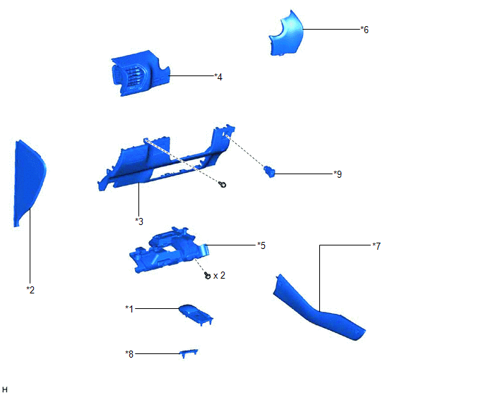
| *1 | CONSOLE ARMREST ASSEMBLY | *2 | INSTRUMENT SIDE PANEL LH |
| *3 | LOWER NO. 1 INSTRUMENT PANEL FINISH PANEL | *4 | NO. 1 INSTRUMENT PANEL SAFETY PAD SUB-ASSEMBLY |
| *5 | NO. 1 INSTRUMENT PANEL UNDER COVER SUB-ASSEMBLY | *6 | NO. 1 SWITCH HOLE BASE |
| *7 | UPPER NO. 2 CONSOLE PANEL GARNISH | *8 | UPPER REAR CONSOLE PANEL |
| *9 | VEHICLE SOUND SWITCH | - | - |
READ NEXT:
 Removal
REMOVAL PROCEDURE 1. REMOVE CONSOLE ARMREST ASSEMBLY Click here 2. REMOVE UPPER REAR CONSOLE PANEL Click here 3. REMOVE UPPER NO. 2 CONSOLE PANEL GARNISH Click here 4. REMOVE INSTRUMENT SI
Inspection
INSPECTION PROCEDURE 1. INSPECT VEHICLE SOUND SWITCH (a) Check the vehicle sound switch on/off operation (1) Measure the resistance according to the value(s) in the table below. Standard Resistance
Installation
INSTALLATION PROCEDURE 1. INSTALL VEHICLE SOUND SWITCH (a) Attach the 2 claws to install the vehicle sound switch. 2. INSTALL LOWER NO. 1 INSTRUMENT PANEL FINISH PANEL Click here 3. INSTALL NO. 1
SEE MORE:
Vehicles Speed Malfunction (B2624)
DESCRIPTION The multiplex tilt and telescopic ECU forms a network with the ECUs of other systems via CAN communication. Each ECU informs the other ECUs that it is connected to the network by sending a specified signal (periodic signal) onto the communication bus on a regular basis. The multiplex til
Rear Door Courtesy Switch Circuit
DESCRIPTION The fold seat control ECU receives the switch operation signal, driving condition signal and rear door open/close signal. Then the fold seat control ECU actives the rear seat according to these signals. WIRING DIAGRAM PROCEDURE 1. INSPECT REAR DOOR COURTESY LIGHT SWITCH ASSEMBLY
© 2016-2026 Copyright www.lexunx.com
