Lexus NX: Installation
INSTALLATION
PROCEDURE
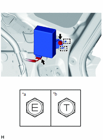
1. INSTALL TIRE PRESSURE WARNING ECU AND RECEIVER
(a) Connect the connector to the tire pressure warning ECU and receiver.
(b) Attach the 2 guides to temporarily install the tire pressure warning ECU and receiver.
| (c) Install the bolt. Torque: for bolt A : 8.3 N·m {85 kgf·cm, 73 in·lbf} for bolt B : 10 N·m {102 kgf·cm, 7 ft·lbf} |
|
2. INSTALL INNER ROOF SIDE GARNISH ASSEMBLY RH
Click here .gif)
3. INSTALL DECK TRIM SIDE PANEL ASSEMBLY RH
Click here
4. INSTALL UPPER DECK TRIM SIDE BOARD RH
Click here
5. INSTALL NO. 1 LUGGAGE COMPARTMENT TRIM HOOK
Click here
6. INSTALL LUGGAGE HOLD BELT STRIKER ASSEMBLY
Click here
7. INSTALL ROPE HOOK ASSEMBLY
Click here
8. INSTALL REAR DOOR OPENING TRIM WEATHERSTRIP RH
Click here
9. INSTALL NO. 1 SEAT LEG ASSEMBLY
-
for Manual Seat: Click here
-
for Power Seat: Click here
10. INSTALL BATTERY SERVICE COVER BOARD
-
for Manual Seat: Click here
-
for Power Seat: Click here
11. INSTALL REAR FLOOR FINISH PLATE
Click here
12. INSTALL REAR FLOOR CARPET
13. INSTALL NO. 2 TOOL BOX SUB-ASSEMBLY
Click here
14. INSTALL NO. 1 TOOL BOX SUB-ASSEMBLY
Click here
15. INSTALL DECK FLOOR BOX RH
Click here
16. INSTALL SPARE TIRE
17. INSTALL NO. 2 DECK BOARD SUB-ASSEMBLY
Click here
18. INSTALL TONNEAU COVER ASSEMBLY
Click here
19. INSTALL REAR SEAT ASSEMBLY
-
for Manual Seat: Click here
-
for Power Seat: Click here
20. CONNECT CABLE TO NEGATIVE AUXILIARY BATTERY TERMINAL
21. INITIALIZATION AFTER RECONECTING AUXILIARY BATTERY TERMINAL
Click here
HINT:
When disconnecting and reconnecting the auxiliary battery, there is an automatic learning function that completes learning when the respective system is used.
Click here
22. INSTALL DECK FLOOR BOX LH
Click here
23. INSTALL REAR DECK FLOOR BOX
Click here
24. INSTALL NO. 3 DECK BOARD SUB-ASSEMBLY
Click here
25. INSTALL DECK BOARD ASSEMBLY
Click here
26. REGISTRATION OF TRANSMITTER ID
Click here
27. INSPECT TIRE PRESSURE WARNING SYSTEM
Click here
28. PERFORM INITIALIZATION
Click here
READ NEXT:
 Components
COMPONENTS ILLUSTRATION *1 TIRE PRESSURE WARNING VALVE AND TRANSMITTER *2 WASHER *3 VALVE CORE *4 GROMMET *5 NUT *6 VALVE CAP N*m (kgf*cm, ft.*lbf): Specified torq
Removal
REMOVAL PROCEDURE 1. REMOVE FRONT WHEEL Click here 2. REMOVE REAR WHEEL Click here 3. REMOVE TIRE PRESSURE WARNING VALVE AND TRANSMITTER (a) Remove the valve cap and valve core to release the air
SEE MORE:
Vehicle Speed Sensor Malfunction (B2415)
DESCRIPTION The headlight ECU sub-assembly LH receives speed signals from the brake booster with master cylinder assembly (skid control ECU) via CAN communication and performs light control. DTC No. Detection Item DTC Detection Condition Trouble Area B2415 Vehicle Speed Sensor Malfunc
GVIF Disconnected (from EMV/MM Integrated Device to Multi Display) (B1575)
DESCRIPTION DTC No. Detection Item DTC Detection Condition Trouble Area B1575 GVIF Disconnected (from EMV/MM Integrated Device to Multi Display) GVIF disconnected (from radio receiver assembly to multi-display assembly)
Harness or connector (GVIF cable)
Multi-display assembly
