Lexus NX: Installation
INSTALLATION
PROCEDURE
1. INSTALL KICK DOOR CONTROL SENSOR
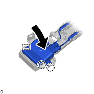
| (a) Insert the guide, attach the 2 claws and install the kick door control sensor to the kick door control bracket as shown in the illustration. NOTICE:
|
|
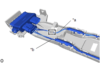
| (b) Connect the wire (red) to the kick door control bracket and attach the clamp. NOTICE:
|
|
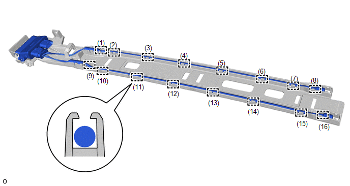
(c) Attach the 16 claws in the order shown in the illustration and connect the antenna.
NOTICE:
Securely insert the antenna into the bracket until it reaches the bottom.
2. INSTALL KICK DOOR CONTROL BRACKET
(a) Attach the 3 guides and temporarily install the kick door control bracket together with the kick door control sensor as shown in the illustration.
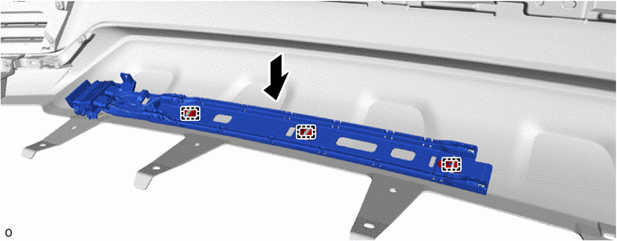
(b) Align the kick door control bracket with the arrow and install the kick door control bracket with the 3 outside moulding retainers as shown in the illustration.
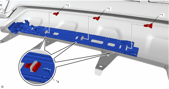
| *1 | Outside Moulding Retainer | - | - |
| *a | Install in this Direction | - | - |
(c) Install the screw.
(d) Attach the 2 wire harness clamps and connect the connector.
NOTICE:
Do not touch the terminal of the kick door control sensor connector.
3. INSTALL REAR BUMPER COVER
Click here .gif)
4. OPERATION CHECK KICK DOOR CONTROL SENSOR
Click here
READ NEXT:
 Power Back Door Control Switch
ComponentsCOMPONENTS ILLUSTRATION *1 BACK DOOR CONTROL SWITCH *2 PULL HANDLE RemovalREMOVAL PROCEDURE 1. REMOVE PULL HANDLE Click here 2. REMOVE BACK DOOR CONTROL SWITCH (a) Detach
Components
COMPONENTS ILLUSTRATION *A w/ Woofer *B w/o Woofer *1 BACK DOOR CENTER GARNISH *2 BACK DOOR LOCK COVER *3 BACK DOOR SIDE GARNISH LH *4 BACK DOOR SIDE GARNISH RH *5
SEE MORE:
Precaution
PRECAUTION TROUBLESHOOTING PRECAUTIONS (a) When there is a malfunction with terminal contact points or part installation problems, removal and installation of the suspected problem parts may return the system to the normal condition either completely or temporarily. (b) Before disconnecting a connec
Charging
CHARGING PROCEDURE 1. PRECAUTION CAUTION: Be sure to read Precaution thoroughly before servicing. Click here 2. INSPECT AUXILIARY BATTERY VOLTAGE Click here 3. PREPARATION FOR HV BATTERY CHARGING CAUTION:
Wear insulated gloves and use insulated tools.
After removing the service plug grip, p
