Lexus NX: Power Back Door Control Switch
Components
COMPONENTS
ILLUSTRATION
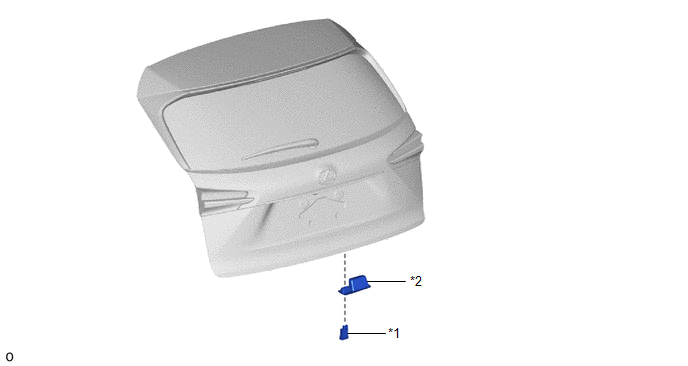
| *1 | BACK DOOR CONTROL SWITCH | *2 | PULL HANDLE |
Removal
REMOVAL
PROCEDURE
1. REMOVE PULL HANDLE
Click here .gif)
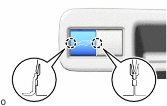
2. REMOVE BACK DOOR CONTROL SWITCH
| (a) Detach the 2 claws and remove the back door control switch. |
|
Inspection
INSPECTION
PROCEDURE
1. INSPECT BACK DOOR CONTROL SWITCH
(a) Check the resistance.
| (1) Measure the resistance according to the value(s) in the table below. Standard Resistance:
If the result is not as specified, replace the back door control switch. |
|
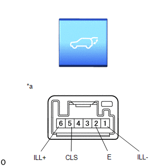
(b) Inspect the illumination operation.
(1) Apply battery voltage to the power back door main switch connector, and check that the back door control switch LED illuminates.
OK:
| Measurement Condition | Specified Condition |
|---|---|
| 6 (ILL+) - Battery positive (+) 1 (ILL-) - Battery negative (-) | LED illuminates |
If the result is not as specified, replace the back door control switch.
Installation
INSTALLATION
PROCEDURE
1. INSTALL BACK DOOR CONTROL SWITCH
(a) Attach the 2 claws to install the back door control switch to the pull handle.
2. INSTALL PULL HANDLE
Click here .gif)
READ NEXT:
 Components
COMPONENTS ILLUSTRATION *A w/ Woofer *B w/o Woofer *1 BACK DOOR CENTER GARNISH *2 BACK DOOR LOCK COVER *3 BACK DOOR SIDE GARNISH LH *4 BACK DOOR SIDE GARNISH RH *5
Removal
REMOVAL CAUTION / NOTICE / HINT HINT:
Use the same procedure for the RH and LH sides.
The procedure listed below is for the LH side.
PROCEDURE 1. REMOVE BACK DOOR CENTER GARNISH Click here
SEE MORE:
Installation
INSTALLATION PROCEDURE 1. INSTALL TIRE PRESSURE WARNING ECU AND RECEIVER (a) Connect the connector to the tire pressure warning ECU and receiver. (b) Attach the 2 guides to temporarily install the tire pressure warning ECU and receiver. (c) Install the bolt. Torque: for bolt A : 8.3 N·m {85 kg
Lost Communication with "Door Control Module B" (U0200)
DESCRIPTION DTC No. Detection Item DTC Detection Condition Trouble Area DTC Output from U0200 Lost Communication with "Door Control Module B" There is no communication from the outer mirror control ECU assembly RH.
Power source circuit of outer mirror control ECU assembly RH
