Lexus NX: Installation
INSTALLATION
PROCEDURE
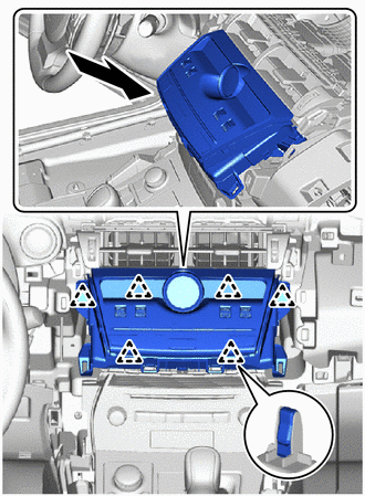
1. INSTALL AIR CONDITIONING CONTROL ASSEMBLY
(a) Connect the 2 connectors.
| (b) Attach the 6 clips to install the air conditioning control assembly. NOTICE: Do not touch the switch, display or clock parts. |
|
2. INSTALL CENTER INSTRUMENT CLUSTER FINISH PANEL ASSEMBLY
Click here .gif)
3. INSTALL NO. 2 INSTRUMENT PANEL SAFETY PAD SUB-ASSEMBLY
Click here
4. INSTALL INSTRUMENT SIDE PANEL RH
Click here
5. INSTALL NO. 1 SWITCH HOLE BASE
Click here
6. INSTALL LOWER NO. 1 INSTRUMENT PANEL FINISH PANEL
Click here
7. INSTALL NO. 1 INSTRUMENT PANEL UNDER COVER SUB-ASSEMBLY
Click here
8. INSTALL NO. 1 INSTRUMENT PANEL SAFETY PAD SUB-ASSEMBLY
Click here
9. INSTALL INSTRUMENT SIDE PANEL LH
Click here
10. INSTALL UPPER NO. 2 CONSOLE PANEL GARNISH
Click here
11. INSTALL UPPER NO. 1 CONSOLE PANEL GARNISH
Click here
12. INSTALL UPPER REAR CONSOLE PANEL
Click here
13. INSTALL REAR CONSOLE ARMREST ASSEMBLY
Click here
14. INSTALL COWL SIDE TRIM BOARD LH
Click here
15. INSTALL DOOR SCUFF PLATE ASSEMBLY LH
Click here
16. INSTALL MULTI-DISPLAY ASSEMBLY
Click here
READ NEXT:
 Components
COMPONENTS ILLUSTRATION *1 AIR CONDITIONER PRESSURE SENSOR - - N*m (kgf*cm, ft.*lbf): Specified torque ● Non-reusable part Compressor oil ND-OIL 11 or equivalent - -
On-vehicle Inspection
ON-VEHICLE INSPECTION PROCEDURE 1. INSPECT AIR CONDITIONER PRESSURE SENSOR (a) Check the wire harness. *a Component without harness connected (Air Conditioner Pressure Sensor) *b Component
SEE MORE:
Hybrid Battery Voltage Isolation Sensor Circuit (P0AA7-727)
DESCRIPTION The hybrid vehicle control ECU monitors the insulation monitoring circuit located in the battery voltage sensor and detects malfunctions. DTC No. Detection Item DTC Detection Condition Trouble Area MIL Warning Indicate P0AA7-727 Hybrid Battery Voltage Isolation Sensor
Utility vehicle precautions
This vehicle belongs to the utility
vehicle class, which has higher
ground clearance and narrower
tread in relation to the height of its
center of gravity.
Utility vehicle feature
Specific design characteristics give
it a higher center of gravity than
ordinary passenger cars. This vehic
