
Lexus NX: On-vehicle Inspection
ON-VEHICLE INSPECTION
PROCEDURE
1. INSPECT AIR CONDITIONER PRESSURE SENSOR
(a) Check the wire harness.
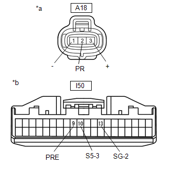
| *a | Component without harness connected (Air Conditioner Pressure Sensor) |
| *b | Component without harness connected (Air Conditioning Amplifier Assembly) |
(1) Disconnect the A18 air conditioner pressure sensor connector.
(2) Disconnect the I50 air conditioning amplifier assembly connector.
(3) Measure the resistance according to the value(s) in the table below.
Standard Resistance:
| Tester Connection | Condition | Specified Condition |
|---|---|---|
| A18-1 (-) - I50-13 (SG-2) | Always | Below 1 Ω |
| A18-2 (PR) - I50-9 (PRE) | Always | Below 1 Ω |
| A18-3 (+) - I50-10 (S5-3) | Always | Below 1 Ω |
| A18-1 (-) - Body ground | Always | 10 kΩ or higher |
| A18-2 (PR) - Body ground | Always | 10 kΩ or higher |
| A18-3 (+) - Body ground | Always | 10 kΩ or higher |
If the resistance is not as specified, repair the wire harness.
| (4) Reconnect the I50 air conditioning amplifier assembly connector. |
|
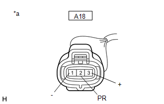
(5) Turn the power switch on (IG).
(6) Measure the voltage according to the value(s) in the table below.
Standard Voltage:
| Tester Connection | Condition | Specified Condition |
|---|---|---|
| A18-3 (+) - Body ground | Power switch on (IG) | 4.75 to 5.25 V |
If the voltage is not as specified, repair the wire harness or replace the air conditioning amplifier assembly.
(b) Check the air conditioner pressure sensor.
(1) Connect the connector to the air conditioner pressure sensor.
(2) Install a manifold gauge set.
(3) Warm up the engine.
(4) Turn the A/C switch on.
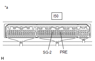
| (5) Measure the voltage according to the value(s) in the table below. HINT: Check from the rear of the connector while it is connected to the air conditioning amplifier assembly. Standard Voltage:
If the voltage is not as specified, replace the air conditioner pressure sensor. |
|
READ NEXT:
 Removal
REMOVAL PROCEDURE 1. RECOVER REFRIGERANT FROM REFRIGERATION SYSTEM Click here 2. REMOVE AIR CONDITIONER PRESSURE SENSOR (a) Disconnect the connector. (b) Using a 27 mm deep socket
Installation
INSTALLATION PROCEDURE 1. INSTALL AIR CONDITIONER PRESSURE SENSOR (a) Remove the vinyl tape from the liquid pipe sub-assembly and the connecting part of the air conditioner pressure sensor. (b) Apply
SEE MORE:
System Description
SYSTEM DESCRIPTION SLIDING ROOF SYSTEM DESCRIPTION (a) The sliding roof system controls the sliding roof operation using the sliding roof drive gear sub-assembly (sliding roof ECU). Operating the map light assembly sliding (slide roof switch) results in electrical power being transmitted to the slid
Essential information
Emergency flashers
The emergency flashers are used to
warn other drivers when the vehicle
has to be stopped in the road due to
a breakdown, etc.
Operating instructions
Press the switch.
All the turn signal lights will flash. To turn
them off, press the switch once again.
■Emergency
