Lexus NX: Installation
INSTALLATION
PROCEDURE
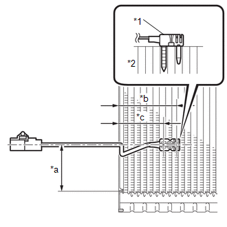
1. INSTALL NO. 1 COOLER THERMISTOR
| (a) Install the No. 1 cooler thermistor as shown in the illustration. NOTICE:
|
|
2. INSTALL NO. 1 COOLER EVAPORATOR SUB-ASSEMBLY
Click here .gif)
3. INSTALL COOLER EXPANSION VALVE
Click here
4. INSTALL QUICK HEATER ASSEMBLY
Click here
5. INSTALL AIR CONDITIONING RADIATOR ASSEMBLY
Click here
READ NEXT:
 Components
COMPONENTS ILLUSTRATION *1 AIR CLEANER CAP SUB-ASSEMBLY *2 AIR CLEANER CASE SUB-ASSEMBLY *3 AIR CLEANER FILTER ELEMENT SUB-ASSEMBLY *4 HEATER ACCESSORY ASSEMBLY *5 HEATER WAT
Removal
REMOVAL PROCEDURE 1. DRAIN ENGINE COOLANT (for Inverter Coolant) Click here 2. REMOVE AIR CLEANER CAP SUB-ASSEMBLY Click here 3. REMOVE AIR CLEANER FILTER ELEMENT SUB-ASSEMBLY Click here 4.
SEE MORE:
Data List / Active Test
DATA LIST / ACTIVE TEST DATA LIST HINT: Using the Techstream to read the Data List allows the values or states of switches, sensors, actuators and other items to be read without removing any parts. This non-intrusive inspection can be very useful because intermittent conditions or signals may be dis
Reassembly
REASSEMBLY CAUTION / NOTICE / HINT HINT:
Use the same procedure for the RH and LH sides.
The procedure listed below is for the LH side.
PROCEDURE 1. INSTALL FRONT DOOR UPPER OUTSIDE MOULDING PAD (a) When using a new front door upper outside moulding sub-assembly LH: (1) Clean the surface of
© 2016-2026 Copyright www.lexunx.com
