Lexus NX: Installation
Lexus NX Service Manual / Vehicle Interior / Interior Panels / Trim / Combination Switch / Installation
INSTALLATION
PROCEDURE
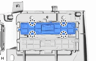
1. INSTALL COMBINATION SWITCH ASSEMBLY (for Upper Side)
| (a) Attach the 4 claws to install the combination switch assembly. |
|
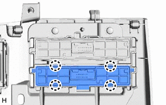
2. INSTALL NO. 2 COMBINATION SWITCH ASSEMBLY (for Lower Side)
| (a) Attach the 4 claws to install the No. 2 combination switch assembly. |
|
3. INSTALL LOWER NO. 1 INSTRUMENT PANEL FINISH PANEL
Click here .gif)
4. INSTALL NO. 1 INSTRUMENT PANEL UNDER COVER SUB-ASSEMBLY
Click here
5. INSTALL NO. 1 INSTRUMENT PANEL SAFETY PAD SUB-ASSEMBLY
Click here
6. INSTALL INSTRUMENT SIDE PANEL LH
Click here
7. INSTALL UPPER NO. 2 CONSOLE PANEL GARNISH
Click here
8. INSTALL CONSOLE ARMREST ASSEMBLY
Click here
READ NEXT:
 Components
COMPONENTS ILLUSTRATION *A for 8 Inch Display *B for 10.3 Inch Display *1 CENTER INSTRUMENT CLUSTER FINISH PANEL ASSEMBLY *2 CONSOLE ARMREST ASSEMBLY *3 INSTRUMENT PANEL FINI
Removal
REMOVAL PROCEDURE 1. REMOVE CONSOLE ARMREST ASSEMBLY Click here 2. REMOVE UPPER REAR CONSOLE PANEL Click here 3. REMOVE UPPER NO. 2 CONSOLE PANEL GARNISH Click here 4. REMOVE UPPER NO. 1 CONS
SEE MORE:
ID BOX EEPROM Malfunction (B2790)
DESCRIPTION When an internal malfunction occurs in the ID code box (immobiliser code ECU), the certification ECU (smart key ECU assembly) stores this DTC. DTC No. Detection Item DTC Detection Condition Trouble Area Note B2790 ID BOX EEPROM Malfunction An internal malfunction occur
Power Retractable Mirrors do not Operate with Power Retract Mirror Switch
DESCRIPTION When the outer mirror switch assembly mirror retract switch is operated, deploy/retract signals are sent to the main body ECU (multiplex network body ECU). The main body ECU (multiplex network body ECU) sends deploy/retract signals to the outer mirror control ECU assembly via CAN communi
© 2016-2026 Copyright www.lexunx.com
