Lexus NX: Removal
REMOVAL
PROCEDURE
1. REMOVE REAR CONSOLE END PANEL SUB-ASSEMBLY (w/ Wireless Charger)
Click here .gif)
2. REMOVE CONSOLE BOX ILLUMINATION LIGHT ASSEMBLY (w/ Wireless Charger)
| (a) Disconnect the connector. |
|
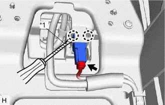
(b) Using a screwdriver, detach the 2 claws and remove the console box illumination light assembly.
HINT:
Tape the screwdriver tip before use.
3. REMOVE CONSOLE BOX ASSEMBLY (w/o Wireless Charger)
Click here
4. REMOVE CONSOLE COMPARTMENT DOOR SUB-ASSEMBLY (w/o Wireless Charger)
Click here
5. REMOVE CONSOLE BOX ILLUMINATION LIGHT ASSEMBLY (w/o Wireless Charger)
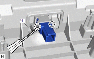
| (a) Remove the 4 screws. |
|
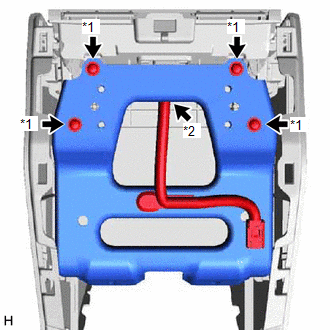
(b) Disconnect the connector and remove the bracket with wire harness.
| (c) Using a screwdriver, detach the 2 claws and remove the console box illumination light assembly. HINT: Tape the screwdriver tip before use. |
|
READ NEXT:
 Inspection
INSPECTION PROCEDURE 1. INSPECT CONSOLE BOX ILLUMINATION LIGHT ASSEMBLY (a) Apply battery voltage to the connector and check the light illumination condition. OK: Measurement Condition Specif
Installation
INSTALLATION PROCEDURE 1. INSTALL CONSOLE BOX ILLUMINATION LIGHT ASSEMBLY (w/ Wireless Charger) (a) Attach the 2 claws to install the console box illumination light assembly. (b) Connec
Footwell Light
ComponentsCOMPONENTS ILLUSTRATION *A for Driver Side *B for Front Passenger Side *1 NO. 1 INSTRUMENT PANEL UNDER COVER SUB-ASSEMBLY *2 NO. 1 INTERIOR ILLUMINATION LIGHT ASSEMBLY L
SEE MORE:
Yaw Rate Sensor (C1234,C1243-C1245,C1279)
DESCRIPTION The skid control ECU (brake booster with master cylinder assembly) receives signals from the yaw rate and acceleration sensor (airbag ECU assembly) via CAN communication. The airbag ECU assembly has a built-in yaw rate and acceleration sensor and detects the vehicle condition using 2 cir
Check For Intermittent Problems
CHECK FOR INTERMITTENT PROBLEMS HINT: Inspect the vehicle ECM using check mode. Intermittent problems are easier to detect with the Techstream when the ECM is in check mode. In check mode, the ECM uses 1 trip detection logic, which is more sensitive to malfunctions than normal mode (default), which
