Lexus NX: Removal
REMOVAL
PROCEDURE
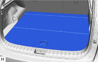
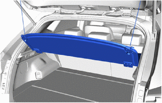
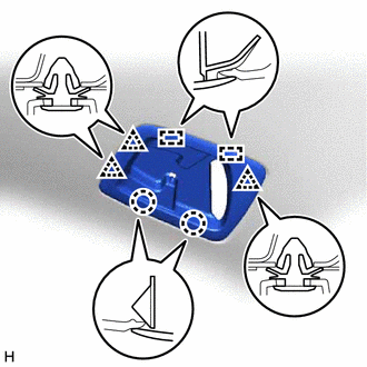
1. REMOVE DECK BOARD ASSEMBLY
| (a) Remove the deck board assembly. |
|
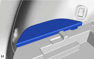
2. REMOVE NO. 3 DECK BOARD SUB-ASSEMBLY
| (a) Remove the No. 3 deck board sub-assembly. |
|
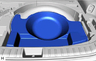
3. REMOVE REAR DECK FLOOR BOX
| (a) Remove the rear deck floor box. |
|
4. REMOVE DECK FLOOR BOX LH
| (a) Remove the 4 clips. |
|
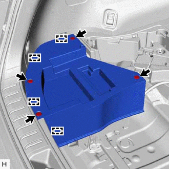
(b) Detach the 4 guides and remove the deck floor box LH.
5. PRECAUTION
CAUTION:
Be sure to read Precaution thoroughly before serving.
Click here .gif)
NOTICE:
After turning the power switch off, there may be a waiting time before disconnecting the negative (-) auxiliary battery terminal.
Click here
6. DISCONNECT CABLE FROM NEGATIVE AUXILIARY BATTERY TERMINAL
CAUTION:
- Wait at least 90 seconds after disconnecting the cable from the negative (-) auxiliary battery terminal to disable the SRS system.
- If the airbag deploys for any reason. it may cause a serious accident.
7. REMOVE REAR SEAT ASSEMBLY (for Manual Seat)
Click here
8. REMOVE REAR SEAT ASSEMBLY (for Power Seat)
Click here
9. REMOVE TONNEAU COVER ASSEMBLY
| (a) Remove the tonneau cover assembly. |
|
10. REMOVE NO. 2 DECK BOARD SUB-ASSEMBLY
| (a) Remove the No. 2 deck board sub-assembly. |
|
11. REMOVE SPARE TIRE
(a) Remove the spare tire.
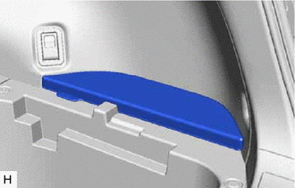
12. REMOVE DECK FLOOR BOX RH
| (a) Remove the 2 clips. |
|
(b) Detach the 4 guides and remove the deck floor box RH.
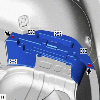
13. REMOVE NO. 1 TOOL BOX SUB-ASSEMBLY
| (a) Remove the screw. |
|
(b) Detach the 2 claws, clip and 5 guides and remove the No. 1 tool box sub-assembly.
14. REMOVE NO. 2 TOOL BOX SUB-ASSEMBLY
| (a) Remove the screw. |
|
(b) Detach the 2 clips and 4 guides and remove the No. 2 tool box sub-assembly.
15. REMOVE REAR FLOOR FINISH PLATE
(a) Detach the 4 claws and 4 clips and remove the rear floor finish plate.
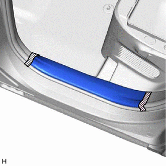
16. REMOVE DOOR SCUFF PLATE ASSEMBLY LH
(a) Put protective tape around the door scuff plate assembly LH.
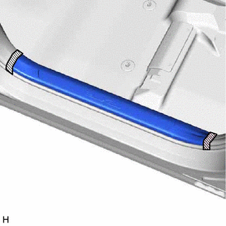
.png) | Protective Tape |
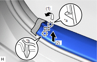
| (b) Detach the 2 claws and guide on the front side of the door scuff plate assembly LH in the order shown in the illustration. HINT:
|
|
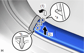
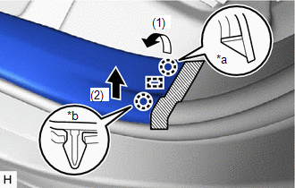
| (c) Detach the 2 claws and guide on the rear side of the door scuff plate assembly LH in the order shown in the illustration. HINT:
|
|
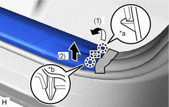
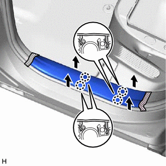
| (d) Pull the door scuff plate assembly LH upwards in the direction indicated by the arrow in the illustration to detach the 6 claws and remove the door scuff plate assembly LH. |
|
17. REMOVE DOOR SCUFF PLATE ASSEMBLY RH
HINT:
Use the same procedure described for the LH side.
18. REMOVE COWL SIDE TRIM BOARD LH
| (a) Remove the cap nut. |
|
(b) Detach the clip and remove the cowl side trim board LH.
19. REMOVE COWL SIDE TRIM BOARD RH
HINT:
Use the same procedure described for the LH side.
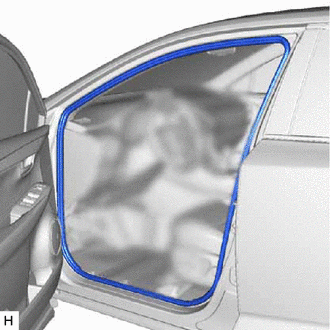
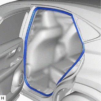
20. REMOVE FRONT DOOR OPENING TRIM WEATHERSTRIP LH
| (a) Remove the front door opening trim weatherstrip LH. |
|
21. REMOVE FRONT DOOR OPENING TRIM WEATHERSTRIP RH
HINT:
Use the same procedure described for the LH side.
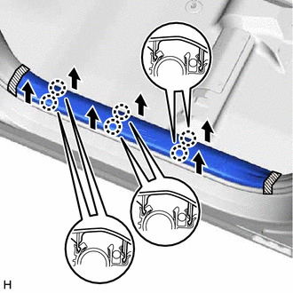
22. REMOVE REAR DOOR SCUFF PLATE LH
(a) Put protective tape around the rear door scuff plate LH.
| | Protective Tape |
| (b) Detach the 2 claws and guide on the front side of the rear door scuff plate LH in the order shown in the illustration. HINT:
|
|
| (c) Detach the 2 claws and guide on the rear side of the rear door scuff plate LH in the order shown in the illustration. HINT:
|
|
| (d) Pull the rear door scuff plate LH upwards in the direction indicated by the arrow in the illustration to detach the 4 claws and remove the rear door scuff plate LH. |
|
23. REMOVE REAR DOOR SCUFF PLATE RH
HINT:
Use the same procedure described for the LH side.
24. REMOVE REAR DOOR OPENING TRIM WEATHERSTRIP LH
| (a) Remove the rear door opening trim weatherstrip LH. |
|
25. REMOVE REAR DOOR OPENING TRIM WEATHERSTRIP RH
HINT:
Use the same procedure described for the LH side.
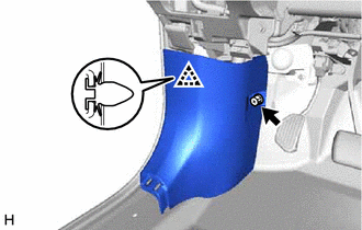
26. REMOVE FRONT PILLAR GARNISH ASSEMBLY LH
| (a) Place your hand in the position shown in the illustration and pull the upper portion of the front pillar garnish assembly LH in the direction indicated by the arrow to detach the 2 front pillar garnish clips. HINT: Make the front pillar garnish assembly LH hang down from the front pillar garnish clip. |
|
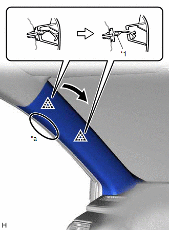
(b) Turn the end of the front pillar garnish clip 90° with needle-nose pliers and remove it from the front pillar garnish assembly LH.
HINT:
Tape the tips of the needle-nose pliers before use.
(c) Detach the 2 guides and remove the front pillar garnish assembly LH.
| *1 | Front Pillar Garnish Clip | - | - |
| *a | 90° | - | - |
| | Protective Tape | - | - |
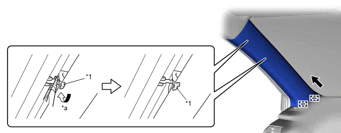
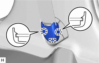
(d) Using your fingers, grasp the parts indicated by the arrows shown in the illustration and remove the front pillar garnish clip.
NOTICE:
If the front pillar garnish clip is damaged, replace it with a new one.
(e) When the front pillar garnish clip cannot be removed by using your fingers:
| (1) While pressing the part indicated by the arrow shown in the illustration with your finger, lift the front pillar garnish clip in direction A. |
|
| (2) While pulling in direction B, push the part indicated by the arrow shown in the illustration with the end of a screwdriver to remove the front pillar garnish clip. NOTICE: If the front pillar garnish clip is damaged, replace it with a new one. |
|
| *a | Protective Cover |
| | Adhesive Tape |
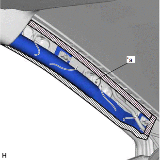
(f) Protect the curtain shield airbag assembly LH.
(1) Completely cover the curtain shield airbag assembly LH with a cloth or nylon sheet and secure the ends of the cover with adhesive tape as shown in the illustration.
NOTICE:
Cover the curtain shield airbag assembly LH with a protective cover as soon as the front pillar garnish assembly LH is removed.
27. REMOVE FRONT PILLAR GARNISH ASSEMBLY RH
HINT:
Use the same procedure described for the LH side.
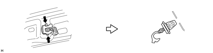
28. REMOVE OUTER LAP BELT ANCHOR COVER
HINT:
Use the same procedure for both outer lap belt anchor covers.
| (a) Detach the 2 claws and guide and remove the outer lap belt anchor cover. |
|
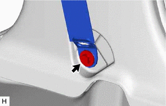
29. DISCONNECT FRONT SEAT OUTER BELT ASSEMBLY LH
| (a) Remove the bolt and disconnect the front seat outer belt assembly LH. |
|
30. DISCONNECT FRONT SEAT OUTER BELT ASSEMBLY RH
HINT:
Use the same procedure described for the LH side.
31. REMOVE LOWER CENTER PILLAR GARNISH LH
| (a) Pull both sides of the lower center pillar garnish LH outward to detach the 2 claws. |
|
(b) Detach the 4 clips and remove the lower center pillar garnish LH.
32. REMOVE LOWER CENTER PILLAR GARNISH RH
HINT:
Use the same procedure described for the LH side.
33. REMOVE CENTER PILLAR GARNISH ASSEMBLY LH
| (a) Remove the 2 clips. |
|
(b) Detach the clip.
(c) Pass the front seat outer belt floor anchor through the center pillar garnish assembly LH, and remove the center pillar garnish LH.
34. REMOVE CENTER PILLAR GARNISH ASSEMBLY RH
HINT:
Use the same procedure described for the LH side.
35. REMOVE NO. 3 BATTERY SERVICE COVER BOARD (for Power Seat)
Click here
36. REMOVE NO. 2 BATTERY SERVICE COVER BOARD (for Power Seat)
Click here
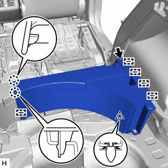
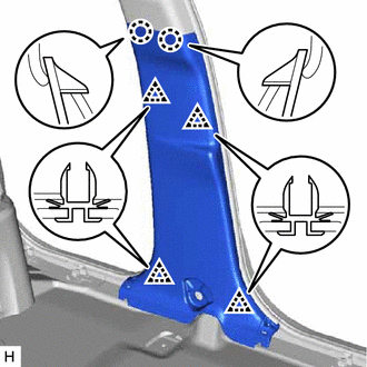
37. REMOVE UPPER DECK TRIM SIDE BOARD LH
| (a) Remove the bolt. |
|
(b) Detach the 10 claws and guide and remove the upper deck trim side board LH.
38. REMOVE UPPER DECK TRIM SIDE BOARD RH
HINT:
Use the same procedure described for the LH side.
39. REMOVE ROPE HOOK ASSEMBLY
HINT:
Use the same procedure for both rope hook assemblies.
(a) Using a screwdriver, detach the 2 claws and open the cover.
| | Protective Tape |
HINT:
Tape the screwdriver tip before use.
| (b) Remove the bolt and rope hook assembly. |
|
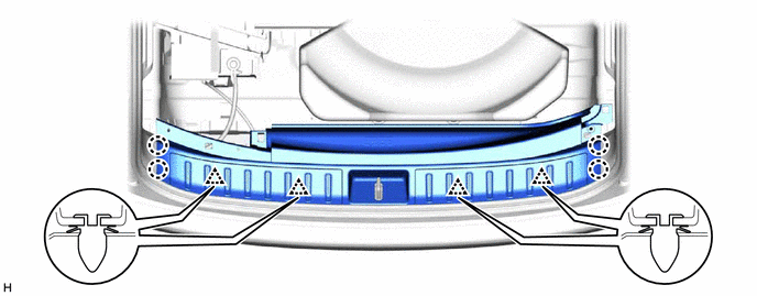
40. REMOVE LUGGAGE HOLD BELT STRIKER ASSEMBLY
HINT:
Use the same procedure for all luggage hold belt striker assemblies.
| (a) Remove the bolt and luggage hold belt striker assembly. |
|
41. REMOVE NO. 1 LUGGAGE COMPARTMENT TRIM HOOK
(a) for LH Side:
(1) Using a screwdriver, push in the claw and turn the No. 1 luggage compartment trim hook in the direction indicated by the arrow shown in the illustration.
HINT:
Tape the screwdriver tip before use.
(2) Pull the No. 1 luggage compartment trim hook in the direction indicated by the arrow in the illustration to detach the claw and guide and remove the No. 1 luggage compartment trim hook.
| | Protective Tape | - | - |
(b) for RH Side:
(1) Using a screwdriver, push in the claw and turn the No. 1 luggage compartment trim hook in the direction indicated by the arrow shown in the illustration.
HINT:
Tape the screwdriver tip before use.
(2) Pull the No. 1 luggage compartment trim hook in the direction indicated by the arrow in the illustration to detach the claw and guide and remove the No. 1 luggage compartment trim hook.
| | Protective Tape | - | - |
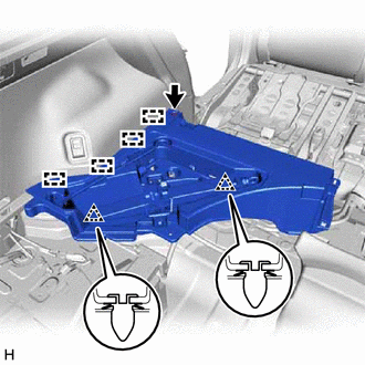
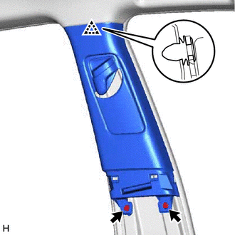
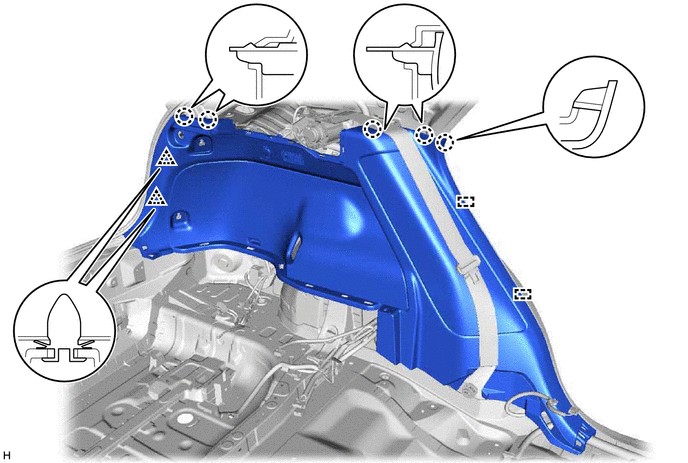
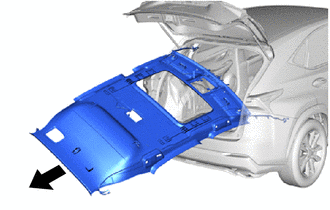
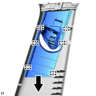
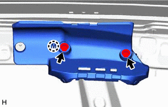
42. REMOVE DECK TRIM SIDE PANEL ASSEMBLY LH
(a) Detach the 5 claws, 2 clips and 2 guides.
(b) Disconnect the connectors and remove the deck trim side panel assembly LH.
43. REMOVE DECK TRIM SIDE PANEL ASSEMBLY RH
HINT:
Use the same procedure described for the LH side.
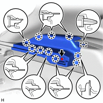
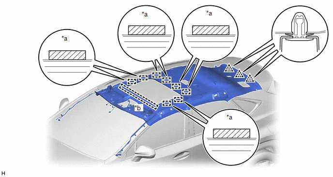
44. REMOVE INNER ROOF SIDE GARNISH ASSEMBLY LH
| (a) Detach the 7 clips and remove the inner roof side garnish assembly LH. |
|
45. REMOVE INNER ROOF SIDE GARNISH ASSEMBLY RH
HINT:
Use the same procedure described for the LH side.
46. REMOVE VISOR BRACKET COVER
HINT:
Use the same procedure for both visor bracket covers.
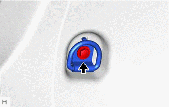
| (a) Using moulding remover A, detach the 4 claws and remove the visor bracket cover. |
|
47. REMOVE VISOR ASSEMBLY LH
| (a) Disconnect the visor assembly LH from the visor holder. |
|
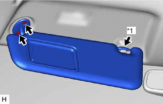
(b) Remove the 2 screws and visor assembly LH.
48. REMOVE VISOR ASSEMBLY RH
HINT:
Use the same procedure described for the LH side.
49. REMOVE VISOR HOLDER
HINT:
Use the same procedure for both visor holders.
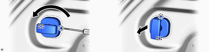
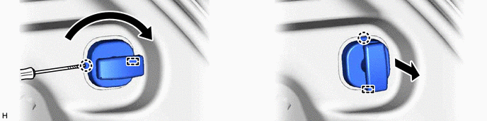
| (a) Turn the visor holder clockwise approximately 45° and pull it out as shown in the illustration. |
|
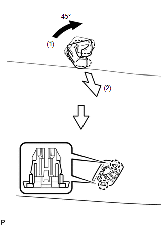
(b) Detach the 2 claws and remove the visor holder.
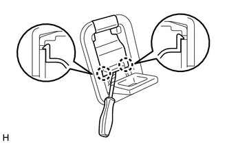
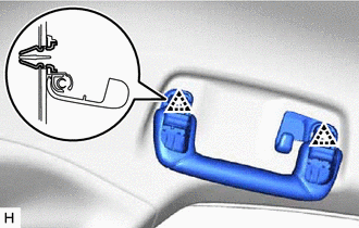
50. REMOVE ASSIST GRIP SUB-ASSEMBLY
HINT:
Use the same procedure for both assist grip sub-assemblies.
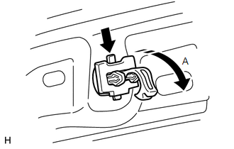
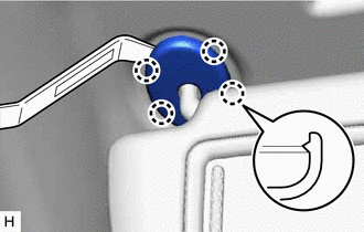
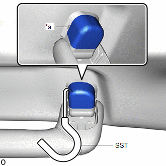
| (a) Insert SST into the cutout of the assist grip cover RH as shown in the illustration. SST: 09813-00010 NOTICE: To prevent the assist grip sub-assembly from being damaged, make sure to insert SST straight into the cutout. |
|
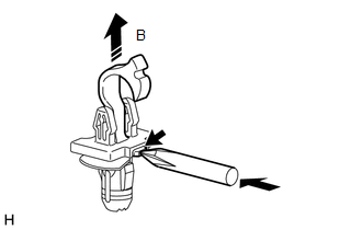
(b) Pull SST as shown in the illustration to detach the claw.
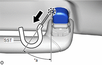
| *a | 30 to 45° |
.png) | Remove in this Direction |
NOTICE:
To prevent the assist grip sub-assembly from being damaged, make sure to only pull SST as shown in the illustration.
HINT:
Use the same procedure for the claw on the other side of the assist grip cover RH.
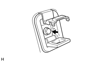
(c) Remove the assist grip cover RH.
HINT:
Use the same procedure for the LH side and RH side.
| (d) Detach the 2 clips and remove the assist grip sub-assembly. |
|
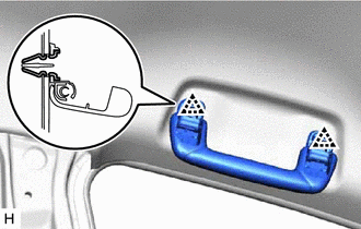
(e) Remove the remaining clip.
51. REMOVE REAR ASSIST GRIP ASSEMBLY LH
| (a) Insert SST into the cutout of the assist grip cover RH as shown in the illustration. SST: 09813-00010 NOTICE: To prevent the rear assist grip assembly LH from being damaged, make sure to insert SST straight into the cutout. |
|
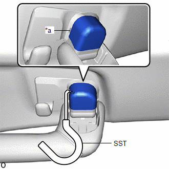
(b) Pull SST as shown in the illustration to detach the claw.
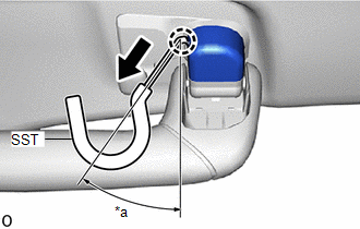
| *a | 30 to 45° |
| | Remove in this Direction |
NOTICE:
To prevent the rear assist grip assembly LH from being damaged, make sure to only pull SST as shown in the illustration.
HINT:
Use the same procedure for the claw on the other side of the assist grip cover RH.
(c) Remove the assist grip cover RH.
HINT:
Use the same procedure for the LH side and RH side.
| (d) Detach the 2 clips and remove the rear assist grip assembly LH. |
|
(e) Remove the remaining clip.
52. REMOVE REAR ASSIST GRIP ASSEMBLY RH
HINT:
Use the same procedure described for the LH side.
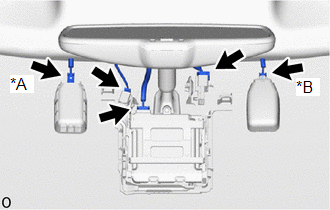
53. REMOVE MAP LIGHT ASSEMBLY
Click here
54. REMOVE SPOT LIGHT ASSEMBLY (ROOM LIGHT)
Click here
55. REMOVE SEAT BELT ANCHOR COVER
| (a) Detach the 2 claws, 3 clips and 2 guides and remove the seat belt anchor cover. |
|
56. REMOVE PROTECTOR (w/ Humidity Sensor)
Click here
57. REMOVE RAIN SENSOR COVER (w/ Rain Sensor)
Click here
58. REMOVE NO. 2 FORWARD RECOGNITION COVER
Click here
59. REMOVE NO. 1 FORWARD RECOGNITION COVER
Click here
60. REMOVE ROOF HEADLINING ASSEMBLY (for Normal Roof)
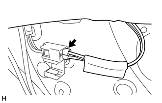
| (a) Disconnect the connectors and detach the clamps from the front pillar LH. |
|
| (b) Disconnect the connectors and detach the clamps from the front pillar RH. |
|
| (c) Disconnect each connector. |
|

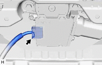
| (d) Disconnect the connector from the rear pillar RH. |
|
(e) Detach the 3 clips.
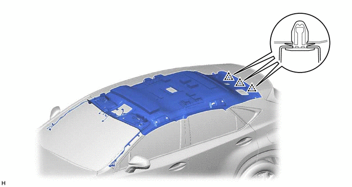
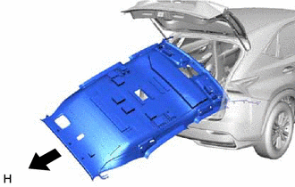
| (f) Turn the roof headlining assembly diagonally and bend slightly to remove it from the back door. NOTICE:
|
|
61. REMOVE ROOF HEADLINING ASSEMBLY (for Sliding Roof)
| (a) Disconnect the connectors and detach the clamps from the front pillar LH. |
|
| (b) Disconnect the connectors and detach the clamps from the front pillar RH. |
|
| (c) Disconnect the drive gear connector. |
|
| (d) Disconnect each connector. |
|
| (e) Disconnect the connector from the rear pillar RH. |
|
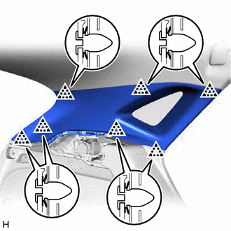
(f) Detach the 3 clips, 8 fasteners and guide.
| *a | Fastener | *b | Guide |
| (g) Turn the roof headlining assembly diagonally and bend slightly to remove it from the back door. NOTICE:
|
|
62. REMOVE FRONT SHOULDER BELT ANCHOR PLATE SUB-ASSEMBLY LH
| (a) Detach the 6 guides and remove the front shoulder belt anchor plate sub-assembly LH. |
|
63. REMOVE FRONT SHOULDER BELT ANCHOR PLATE SUB-ASSEMBLY RH
HINT:
Use the same procedure described for the LH side.
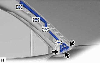
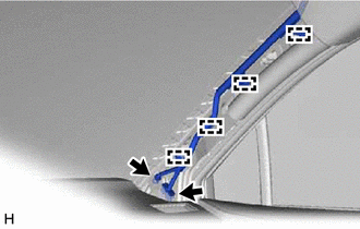
64. REMOVE CURTAIN SHIELD AIRBAG ASSEMBLY LH
Click here
65. REMOVE CURTAIN SHIELD AIRBAG ASSEMBLY RH
HINT:
Use the same procedure described for the LH side.
66. REMOVE REAR SIDE RAIL SPACER LH
| (a) Remove the 2 bolts. |
|
(b) Detach the claw and remove the rear side rail spacer LH.
67. REMOVE REAR SIDE RAIL SPACER RH
HINT:
Use the same procedure described for the LH side.
68. REMOVE REAR NO. 2 SIDE RAIL SPACER LH
| (a) Remove the 2 bolts. |
|

(b) Detach the 2 claws and remove the rear No. 2 side rail spacer LH.
69. REMOVE REAR NO. 2 SIDE RAIL SPACER RH
HINT:
Use the same procedure described for the LH side.
READ NEXT:
 Disassembly
DISASSEMBLY PROCEDURE 1. REMOVE CHILD RESTRAINT SEAT TETHER ANCHOR COVER (a) Detach the 2 claws, 2 guides and remove the child restraint seat tether anchor cover. 2. REMOVE VANITY LIGHT
Reassembly
REASSEMBLY PROCEDURE 1. INSTALL NO. 2 ANTENNA CORD SUB-ASSEMBLY Click here 2. INSTALL NO. 4 ROOF HEADLINING SUPPORT (for Normal Roof) (a) Align the No. 4 roof headlining support with the marking
Installation
INSTALLATION CAUTION / NOTICE / HINT HINT: A bolt without a torque specification is shown in the standard bolt chart. Click here PROCEDURE 1. INSTALL REAR NO. 2 SIDE RAIL SPACER LH (a) Attach the 2
SEE MORE:
Security Horn Assembly
ComponentsCOMPONENTS ILLUSTRATION *1 SECURITY HORN ASSEMBLY - - N*m (kgf*cm, ft.*lbf): Specified torque - - RemovalREMOVAL PROCEDURE 1. REMOVE SECURITY HORN ASSEMBLY (a) Remove the bolt and detach the guide. (b) Disconnect the connector and remove the securit
PIG Power Supply Voltage (C1552,C1554)
DESCRIPTION When a problem occurs in the power steering system, the power source relay circuit is shut off to stop the power assist. DTC No. Detection Item DTC Detection Condition Trouble Area Warning Indicate Return-to-normal Condition C1552 PIG Power Supply Voltage PIG power s
