Lexus NX: Installation
INSTALLATION
PROCEDURE
1. INSTALL CLOCK ASSEMBLY
| (a) Attach the 2 claws to install the clock assembly. |
|
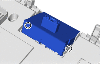
2. INSTALL AIR CONDITIONING CONTROL ASSEMBLY
| (a) Connect the connectors. |
|
.png)
(b) Attach the 6 clips to install the air conditioning control assembly.
3. INSTALL CENTER INSTRUMENT CLUSTER FINISH PANEL ASSEMBLY
Click here .gif)
4. INSTALL MULTI-DISPLAY ASSEMBLY WITH BRACKET
Click here
5. INSTALL INSTRUMENT PANEL FINISH PLATE
Click here
6. INSTALL NO. 2 INSTRUMENT PANEL SAFETY PAD SUB-ASSEMBLY
Click here
7. INSTALL INSTRUMENT SIDE PANEL RH
Click here
8. INSTALL NO. 1 SWITCH HOLE BASE
Click here
9. INSTALL LOWER NO. 1 INSTRUMENT PANEL FINISH PANEL
Click here
10. INSTALL NO. 1 INSTRUMENT PANEL UNDER COVER SUB-ASSEMBLY
Click here
11. INSTALL NO. 1 INSTRUMENT PANEL SAFETY PAD SUB-ASSEMBLY
Click here
12. INSTALL INSTRUMENT SIDE PANEL LH
Click here
13. INSTALL UPPER NO. 2 CONSOLE PANEL GARNISH
Click here
14. INSTALL UPPER NO. 1 CONSOLE PANEL GARNISH
Click here
15. INSTALL UPPER REAR CONSOLE PANEL
Click here
16. INSTALL CONSOLE ARMREST ASSEMBLY
Click here
READ NEXT:
 Parts Location
PARTS LOCATION ILLUSTRATION *1 CLOCK ASSEMBLY *2 COMBINATION METER ASSEMBLY *3 RADIO RECEIVER ASSEMBLY *4 INSTRUMENT PANEL JUNCTION BLOCK ASSEMBLY - ACC FUSE - PANEL FUSE *5
System Diagram
SYSTEM DIAGRAM
SEE MORE:
Accumulator Low Pressure (C1256)
DESCRIPTION The accumulator pressure sensor is built into the brake actuator (brake booster with master cylinder assembly) and detects the accumulator pressure. The skid control ECU (brake booster with master cylinder assembly) turns on the brake warning light / red (malfunction) and brake warning l
Drive Motor "A" Control Module (P0A1B-554,P0A1C-169)
DTC SUMMARY MALFUNCTION DESCRIPTION These DTCs indicate that a large current flowed in the boost converter. The cause of this malfunction may be one of the following: Internal inverter malfunction
Inverter internal circuit malfunction
Malfunction in ECU that controls the inverter
DESCRIPTION
