Lexus NX: Installation
INSTALLATION
CAUTION / NOTICE / HINT
NOTICE:
When replacing the combination meter assembly, make sure to replace it with a new one.
PROCEDURE
1. INSTALL COMBINATION METER ASSEMBLY
| (a) Connect the connectors and attach the clamp. |
|
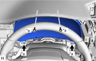
(b) Install the combination meter assembly with the 4 screws.
2. INSTALL INSTRUMENT CLUSTER FINISH PANEL SUB-ASSEMBLY
Click here .gif)
3. INSTALL CENTER INSTRUMENT CLUSTER FINISH PANEL ASSEMBLY
Click here
4. INSTALL MULTI-DISPLAY ASSEMBLY WITH BRACKET
Click here
5. INSTALL INSTRUMENT PANEL FINISH PLATE
Click here
6. INSTALL NO. 2 INSTRUMENT PANEL SAFETY PAD SUB-ASSEMBLY
Click here
7. INSTALL INSTRUMENT SIDE PANEL RH
Click here
8. INSTALL NO. 1 SWITCH HOLE BASE
Click here
9. INSTALL LOWER NO. 1 INSTRUMENT PANEL FINISH PANEL
Click here
10. INSTALL NO. 1 INSTRUMENT PANEL UNDER COVER SUB-ASSEMBLY
Click here
11. INSTALL NO. 1 INSTRUMENT PANEL SAFETY PAD SUB-ASSEMBLY
Click here
12. INSTALL INSTRUMENT SIDE PANEL LH
Click here
13. INSTALL UPPER NO. 2 CONSOLE PANEL GARNISH
Click here
14. INSTALL UPPER NO. 1 CONSOLE PANEL GARNISH
Click here
15. INSTALL UPPER REAR CONSOLE PANEL
Click here
16. INSTALL CONSOLE ARMREST ASSEMBLY
Click here
17. ENABLE AUTOAWAY/RETURN FUNCTION (for Power Tilt and Power Telescopic Steering Column)
(a) Restore the autoaway/return function setting to the previous condition by changing the customize parameter.
Click here
READ NEXT:
 Components
COMPONENTS ILLUSTRATION *1 DECK FLOOR BOX LH *2 NO. 3 DECK BOARD SUB-ASSEMBLY *3 REAR DECK FLOOR BOX *4 NEGATIVE AUXILIARY BATTERY TERMINAL N*m (kgf*cm, ft.*lbf): Specified
Removal
REMOVAL PROCEDURE 1. DISABLE AUTOAWAY/RETURN FUNCTION (for Power Tilt and Power Telescopic Steering Column) (a) Disable the autoaway/return function by changing the customize parameter. Click here C
SEE MORE:
Software Incompatibility with Body Control Module Invalid/Incompatible Software Component (U032257)
DESCRIPTION The forward recognition camera receives vehicle specification information from the main body ECU (multiplex network body ECU) via the CAN communication line. When the value of the vehicle specification information sent from the main body ECU (multiplex network body ECU) does not match th
Parts Location
PARTS LOCATION ILLUSTRATION *1 ENGINE ROOM RELAY BLOCK
- AM2 FUSE
*2 WIRELESS DOOR LOCK BUZZER *3 DOOR CONTROL RECEIVER - - ILLUSTRATION *A w/o Power Back Door System *B w/ Power Back Door System *1 BACK DOOR COURTESY LIGHT SWITCH ASSEMBLY *2 BACK DOO
