Lexus NX: Components
COMPONENTS
ILLUSTRATION
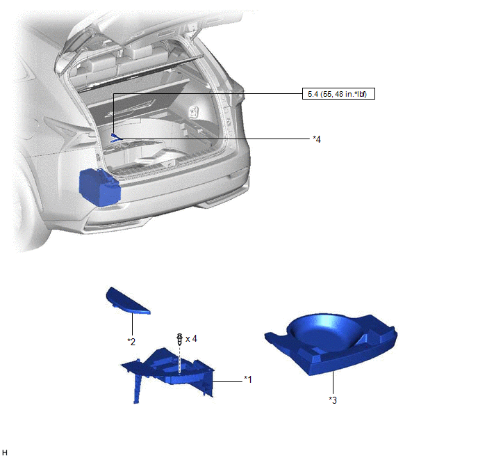
| *1 | DECK FLOOR BOX LH | *2 | NO. 3 DECK BOARD SUB-ASSEMBLY |
| *3 | REAR DECK FLOOR BOX | *4 | NEGATIVE AUXILIARY BATTERY TERMINAL |
.png) | N*m (kgf*cm, ft.*lbf): Specified torque | - | - |
ILLUSTRATION
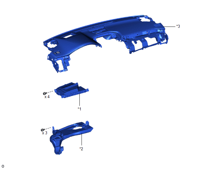
| *1 | METER MIRROR SUB-ASSEMBLY (HEADUP DISPLAY) | *2 | NO. 1 HEATER TO REGISTER DUCT SUB-ASSEMBLY |
| *3 | UPPER INSTRUMENT PANEL SUB-ASSEMBLY | - | - |
ILLUSTRATION
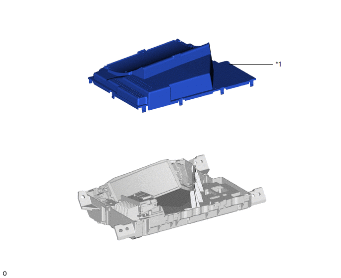
| *1 | NO. 1 COMBINATION METER MIRROR PLATE | - | - |
READ NEXT:
 Removal
REMOVAL PROCEDURE 1. DISABLE AUTOAWAY/RETURN FUNCTION (for Power Tilt and Power Telescopic Steering Column) (a) Disable the autoaway/return function by changing the customize parameter. Click here C
Disassembly
DISASSEMBLY PROCEDURE 1. REMOVE NO. 1 COMBINATION METER MIRROR PLATE (a) Detach the 10 claws and remove the No. 1 combination meter mirror plate from the meter mirror sub-assembly (headup display).
Reassembly
REASSEMBLY PROCEDURE 1. INSTALL NO. 1 COMBINATION METER MIRROR PLATE (a) Attach the 10 claws to install the No. 1 combination meter mirror plate to the meter mirror sub-assembly (headup display).
SEE MORE:
DC / DC Converter Performance (P0A94-553)
DTC SUMMARY MALFUNCTION DESCRIPTION This DTC indicates when the temperature of the boost converter has become abnormal. The cause of this malfunction may be one of the following: Area Main Malfunction Description Step Inverter low-voltage circuit The connectors are not connected properl
Diagnosis System
DIAGNOSIS SYSTEM CHECK DLC3 (a) Check the DLC3. Click here INSPECT AUXILIARY BATTERY VOLTAGE (a) Check the auxiliary battery voltage. Standard voltage: 11 to 14 V (power switch off) If the voltage is below 11 V, recharge or replace the auxiliary battery.
© 2016-2026 Copyright www.lexunx.com
