Lexus NX: Installation
INSTALLATION
PROCEDURE
1. INSTALL INSTRUMENT PANEL PASSENGER AIRBAG ASSEMBLY
(a) Attach the 3 hooks on the side of the airbag door facing the front of the vehicle and set the instrument panel passenger airbag assembly onto the airbag door.
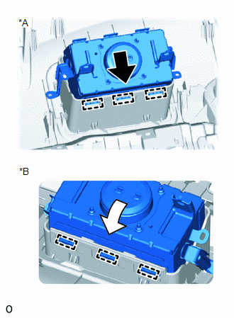
| *A | Front of the Vehicle |
| *B | Rear of the Vehicle |
.png) | Set |
.png) | Slowly Pull |
(b) Slowly pull the instrument panel passenger airbag assembly in the direction indicated by the arrow shown in the illustration to attach the 3 hooks on the side of the airbag door facing the rear of the vehicle and install the instrument panel passenger airbag assembly.
(c) Install the 2 screws.
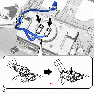
2. INSTALL NO. 2 INSTRUMENT PANEL WIRE
(a) Attach the 2 wire harness clamps to install the No. 2 instrument panel wire.
| (b) Connect the airbag connector and push the connector lock. NOTICE:
HINT: Use the same procedure to connect the airbag connector on the other side. |
|
3. INSTALL UPPER INSTRUMENT PANEL
Click here .gif)
4. CONNECT CABLE TO NEGATIVE AUXILIARY BATTERY TERMINAL
(a) Connect the cable to the negative (-) auxiliary battery terminal and tighten the nut.
Torque:
5.4 N·m {55 kgf·cm, 48 in·lbf}
5. INITIALIZATION AFTER RECONNECTING AUXILIARY BATTERY TERMINAL
Click here
HINT:
When disconnecting and reconnecting the auxiliary battery, there is an automatic learning function that completes learning when the respective system is used.
Click here
6. INSTALL DECK FLOOR BOX LH
Click here
7. INSTALL REAR DECK FLOOR BOX
Click here
8. INSTALL NO. 3 DECK BOARD SUB-ASSEMBLY
Click here
9. PERFORM DIAGNOSTIC SYSTEM CHECK
Click here
10. CHECK SRS WARNING LIGHT
Click here
READ NEXT:
 Disposal
DISPOSAL CAUTION / NOTICE / HINT CAUTION: Before performing pre-disposal deployment of any SRS part, review and closely follow all applicable environmental and hazardous material regulations. Pre-disp
Components
COMPONENTS ILLUSTRATION *1 DECK FLOOR BOX LH *2 NO. 3 DECK BOARD SUB-ASSEMBLY *3 REAR DECK FLOOR BOX *4 AUXILIARY BATTERY NEGATIVE TERMINAL N*m (kgf*cm, ft.*lbf): Specified
SEE MORE:
Disassembly
DISASSEMBLY CAUTION / NOTICE / HINT CAUTION: Wear protective gloves. Sharp areas on the parts may injure your hands. PROCEDURE 1. REMOVE REAR SEAT CUSHION LOCK HOOK NOTICE:
Perform the following only when replacing the rear seat cushion lock hook.
Do not reuse the rear seat cushion lock hook af
Disassembly
DISASSEMBLY PROCEDURE 1. REMOVE HOOD INSULATOR (a) Using a clip remover, remove the 7 clips. (b) Detach the 2 guides and remove the hood insulator. 2. REMOVE HOOD TO FRONT FENDER SEAL LH (a) Using a clip remover, detach the 2 claws and remove the hood to front fender seal LH.
