Lexus NX: Removal
REMOVAL
PROCEDURE
1. REMOVE UPPER INSTRUMENT PANEL SUB-ASSEMBLY
Click here .gif)
2. REMOVE NO. 1 HEATER TO REGISTER DUCT SUB-ASSEMBLY
Click here
3. REMOVE NAVIGATION ANTENNA ASSEMBLY WITH BRACKET
| (a) Detach the 2 clamps. |
|
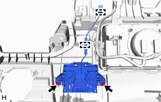
(b) Remove the 2 screws and navigation antenna assembly with bracket.
4. REMOVE ANTENNA CORD SUB-ASSEMBLY
| (a) Detach the 4 claws. |
|
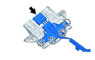
(b) Disconnect the connector and remove the antenna cord sub-assembly.
5. REMOVE NAVIGATION ANTENNA BRACKET
| (a) Detach the 2 claws. |
|
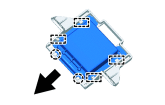
(b) Detach the 4 guides and remove the navigation antenna assembly as shown in the illustration.
6. REMOVE NAVIGATION ANTENNA ASSEMBLY
READ NEXT:
 Inspection
INSPECTION PROCEDURE 1. INSPECT NAVIGATION ANTENNA ASSEMBLY (a) Measure the resistance according to the value(s) in the table below. Standard Resistance: Tester Antenna Tester Connection Co
Installation
INSTALLATION PROCEDURE 1. INSTALL NAVIGATION ANTENNA ASSEMBLY 2. INSTALL NAVIGATION ANTENNA BRACKET (a) Attach the 4 guides to install the navigation antenna assembly as shown in the illustration.
Navigation Ecu
ComponentsCOMPONENTS ILLUSTRATION *1 NAVIGATION ECU *2 NO. 1 RADIO BRACKET *3 NO. 2 RADIO BRACKET *4 RADIO RECEIVER ASSEMBLY WITH BRACKET *5 NAVIGATION WIRE - - Remo
SEE MORE:
Components
COMPONENTS ILLUSTRATION *1 DECK FLOOR BOX LH *2 NO. 3 DECK BOARD SUB-ASSEMBLY *3 REAR DECK FLOOR BOX *4 NEGATIVE AUXILIARY BATTERY TERMINAL N*m (kgf*cm, ft.*lbf): Specified torque - - ILLUSTRATION *1 ECU INTEGRATION BOX RH *2 GLOVE COMPARTMENT DOOR ASSEMBL
D-Seat ECU Vehicle Information Reading/Writing Process Malfunction (B15F8)
DESCRIPTION This DTC is stored when items controlled by the position control ECU assembly (driver seat) cannot be customized via the audio and visual system vehicle customization screen. HINT: The position control ECU assembly (driver seat) controls the front power seat control system (w/ Memory) re
© 2016-2026 Copyright www.lexunx.com
