Lexus NX: Mirror Heater does not Operate with Rear Defogger Switch
DESCRIPTION
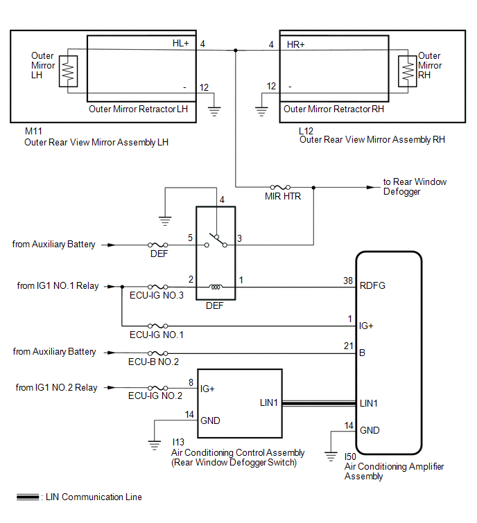
When the rear window defogger switch (mirror heater switch) on the air conditioning control assembly is pressed, the operation signal is transmitted to the air conditioning amplifier assembly via LIN communication. When the air conditioning amplifier assembly receives the signal, it turns on the defogger relay to operate the mirror heaters.
WIRING DIAGRAM
CAUTION / NOTICE / HINT
NOTICE:
Inspect the fuses for circuits related to this system before performing the following procedure.
PROCEDURE
| 1. | PERFORM ACTIVE TEST USING TECHSTREAM (DEFOGGER RELAY [REAR]) |
(a) Connect the Techstream to the DLC3.
(b) Turn the power switch on (IG).
(c) Turn the Techstream on.
(d) Enter the following menus: Body Electrical / Air Conditioner / Active Test.
(e) Perform the Active Test according to the display on the Techstream.
Body Electrical > Air Conditioner > Active Test| Tester Display | Measurement Item | Control Range | Diagnostic Note |
|---|---|---|---|
| Defogger Relay (Rear) | Mirror Heater | OFF/ON | - |
| Tester Display |
|---|
| Defogger Relay (Rear) |
| Result | Proceed to |
|---|---|
| Mirror heater operation on both mirrors are not normal | A |
| Mirror heater operation on RH side mirror is not normal | B |
| Mirror heater operation on LH side mirror is not normal | C |
| B | .gif) | GO TO STEP 4 |
| C | | GO TO STEP 6 |
|
.gif)
| 2. | CHECK WINDOW DEFOGGER SYSTEM |
(a) Check the window defogger system operation.
Click here .gif)
OK:
The window defogger system operates normally.
| NG | | GO TO WINDOW DEFOGGER SYSTEM |
|
| 3. | CHECK HARNESS AND CONNECTOR (DEF RELAY - OUTER REAR VIEW MIRROR ASSEMBLY) |
(a) Disconnect the M11*1 or L12*2 outer rear view mirror assembly connector.
- *1: for LH Side
- *2: for RH Side
(b) Measure the voltage according to the value(s) in the table below.
Standard Voltage:
for LH Side
| Tester Connection | Switch Condition | Specified Condition |
|---|---|---|
| M11-4 (HL+) - Body ground | Power switch on (IG), rear window defogger switch on | 11 to 14 V |
for RH Side
| Tester Connection | Switch Condition | Specified Condition |
|---|---|---|
| L12-4 (HR+) - Body ground | Power switch on (IG), rear window defogger switch on | 11 to 14 V |
| OK | | USE SIMULATION METHOD TO CHECK |
| NG | | REPAIR OR REPLACE HARNESS OR CONNECTOR |
| 4. | INSPECT OUTER MIRROR RH |
(a) Remove the outer mirror RH.
Click here
(b) Inspect the outer mirror RH.
Click here
| NG | | REPLACE OUTER MIRROR RH |
|
| 5. | CHECK HARNESS AND CONNECTOR (DEF RELAY - OUTER REAR VIEW MIRROR ASSEMBLY RH AND BODY GROUND) |
(a) Disconnect the L12 outer rear view mirror assembly RH connector.
(b) Measure the voltage according to the value(s) in the table below.
Standard Voltage:
| Tester Connection | Switch Condition | Specified Condition |
|---|---|---|
| L12-4 (HR+) - L12-12 (-) | Power switch on (IG), rear window defogger switch on | 11 to 14 V |
| L12-4 (HR+) - Body ground | Power switch on (IG), rear window defogger switch on | 11 to 14 V |
| OK | | REPLACE OUTER MIRROR RETRACTOR RH |
| NG | | REPAIR OR REPLACE HARNESS OR CONNECTOR |
| 6. | INSPECT OUTER MIRROR LH |
(a) Remove the outer mirror LH.
Click here
(b) Inspect the outer mirror LH.
Click here
| NG | | REPLACE OUTER MIRROR LH |
|
| 7. | CHECK HARNESS AND CONNECTOR (DEF RELAY - OUTER REAR VIEW MIRROR ASSEMBLY LH AND BODY GROUND) |
(a) Disconnect the M11 outer rear view mirror assembly LH connector.
(b) Measure the voltage according to the value(s) in the table below.
Standard Voltage:
| Tester Connection | Switch Condition | Specified Condition |
|---|---|---|
| M11-4 (HL+) - M11-12 (-) | Power switch on (IG), rear window defogger switch on | 11 to 14 V |
| M11-4 (HL+) - Body ground | Power switch on (IG), rear window defogger switch on | 11 to 14 V |
| OK | | REPLACE OUTER MIRROR RETRACTOR LH |
| NG | | REPAIR OR REPLACE HARNESS OR CONNECTOR |
READ NEXT:
 Power Retractable Mirrors do not Operate with Power Retract Mirror Switch
DESCRIPTION When the outer mirror switch assembly (mirror retract switch) is operated, a retract/return signal is received by the main body ECU (multiplex network body ECU). The main body ECU (multipl
AUTO Power Retract Mirrors do not operate
DESCRIPTION The outer mirror switch assembly (mirror retract switch) sends the auto retractable outer mirror switch signal to the main body ECU (multiplex network body ECU). The main body ECU (multipl
Relay
On-vehicle InspectionON-VEHICLE INSPECTION PROCEDURE 1. INSPECT NO. 1 MIRROR RELAY (a) Remove the No. 1 mirror relay. (b) Measure the resistance according to the value(s) in the table below. Stand
SEE MORE:
Side doors
The vehicle can be locked and
unlocked using the entry function,
wireless remote control or door
lock switch.
Unlocking and locking the doors
from the outside
■ Using the smart access system with
push-button start
Carry the electronic key to enable this
function.
Grip the driver's d
Vehicle Speed Signal Malfunction (B2282,B2283)
DESCRIPTION DTC B2282 is stored when the vehicle speed signal sent by the combination meter assembly via direct line and the vehicle speed signal sent via CAN communication do not match. DTC B2283 is stored when a malfunction in the vehicle speed sensor is detected. DTC No. Detection Item DTC
