Lexus NX: Removal
REMOVAL
CAUTION / NOTICE / HINT
HINT:
- Use the same procedure for the RH and LH sides.
- The following procedure is for the LH side.
NOTICE:
- While the auxiliary battery is connected, even if the power switch is off, the brake control system activates when the brake pedal is depressed or the door courtesy switch is turned on. Therefore, even if only brake pads are to be removed and installed, be sure to perform the Disable Brake Control procedure and disconnect the cable from the negative (-) terminal of the auxiliary battery before beginning work.
- If the RH side flexible hose and LH side flexible hose are both removed from the vehicle at the same time, place an identification mark on each hose so that it can be reinstalled to its original position.
PROCEDURE
1. REMOVE NO. 3 DECK BOARD SUB-ASSEMBLY
Click here .gif)
2. REMOVE REAR DECK FLOOR BOX
Click here
3. REMOVE DECK FLOOR BOX LH
Click here
4. DISABLE BRAKE CONTROL
Click here
5. REMOVE FRONT WHEEL
Click here
6. DRAIN BRAKE FLUID
NOTICE:
Wash off brake fluid immediately if it comes in contact with any painted surface.
7. REMOVE FRONT FLEXIBLE HOSE
(a) w/ AVS:
| (1) Disconnect the brake tube labeled A from the flexible hose using a union nut wrench while holding the flexible hose with a wrench. NOTICE:
|
|
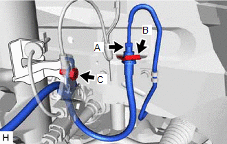
(2) Remove the clip labeled B.
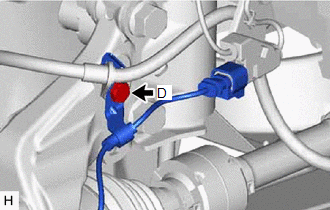
| (3) Remove the bolt labeled D, speed sensor clamp and flexible hose bracket from the steering knuckle. |
|
| (4) Remove the bolt labeled C, and then remove the front speed sensor bracket and front flexible hose bracket from the absorber bracket in that order. |
|
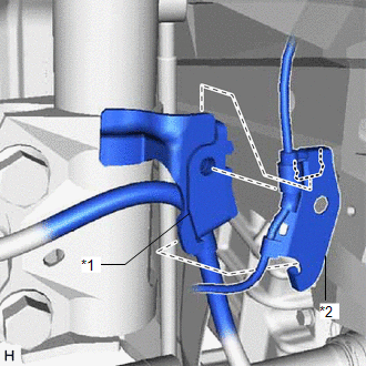
(b) w/o AVS:
| (1) Disconnect the brake tube labeled A from the flexible hose using a union nut wrench while holding the flexible hose with a wrench. NOTICE:
|
|
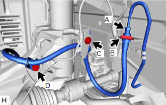
(2) Remove the clip labeled B.
(3) Remove the clip labeled D and flexible hose bracket from the steering knuckle.
| (4) Remove the bolt labeled C, and then remove the front speed sensor bracket and front flexible hose bracket from the absorber bracket in the order. |
|
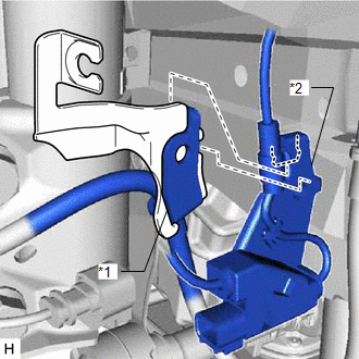
| (c) Remove the union bolt and gasket, and then remove the flexible hose from the disc brake cylinder. |
|
.png)
READ NEXT:
 Installation
INSTALLATION CAUTION / NOTICE / HINT HINT:
Use the same procedure for the RH and LH sides.
The following procedure is for the LH side.
NOTICE:
Since the RH side flexible hose and LH side fl
SEE MORE:
Rear Door Courtesy Switch Circuit
DESCRIPTION The fold seat control ECU receives the switch operation signal, driving condition signal and rear door open/close signal. Then the fold seat control ECU actives the rear seat according to these signals. WIRING DIAGRAM PROCEDURE 1. INSPECT REAR DOOR COURTESY LIGHT SWITCH ASSEMBLY
Precaution
PRECAUTION NOTICE: When disassembling the headlight assembly, use static electricity countermeasures SST (desktop antistatic mat set) and observe all precautions to prevent damage to the system by electrostatic discharge (ESD). STATIC ELECTRICITY COUNTERMEASURES SST SST:Desktop antistatic mat set (0
