Lexus NX: Installation
INSTALLATION
CAUTION / NOTICE / HINT
HINT:
- Use the same procedure for the RH and LH sides.
- The following procedure is for the LH side.
NOTICE:
- Since the RH side flexible hose and LH side flexible hose are not interchangeable, verify the part numbers when installing the front flexible hoses.
- If the front flexible hoses are to be reused, connect them after checking the identification marks placed when each hose was disconnected.
PROCEDURE
1. INSTALL FRONT FLEXIBLE HOSE
(a) Connect the flexible hose to the disc brake cylinder with a new gasket and new union bolt.
Torque:
30.4 N·m {310 kgf·cm, 22 ft·lbf}
HINT:
Insert the flexible hose lock securely into the lock hole in the cylinder.
(b) w/ AVS:
| (1) Set the flexible hose clamp on the flexible hose bracket. |
|
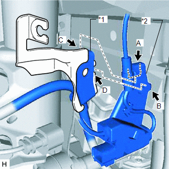
(2) Hook the hook labeled A of the front speed sensor bracket onto the part of the absorber bracket labeled C.
(3) Insert the hook labeled B of the front speed sensor bracket into the part of the absorber bracket labeled D.
(4) Install the No. 2 front flexible hose and front speed sensor bracket to the absorber bracket with the bolt.
Torque:
18.8 N·m {192 kgf·cm, 14 ft·lbf}
| (5) Install the flexible hose bracket and speed sensor clamp to the steering knuckle with the bolt labeled D. Torque: 18.8 N·m {192 kgf·cm, 14 ft·lbf} |
|
.png)
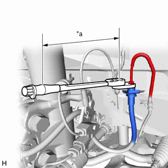
(6) Install a new clip to the front flexible hose.
NOTICE:
Install the clip as far as it will go.
| (7) Using a union nut wrench, connect the flexible hose to the brake tube labeled A while holding the flexible hose with a wrench. Torque: Specified tightening torque : 15.2 N·m {155 kgf·cm, 11 ft·lbf} HINT:
NOTICE:
|
|
(c) w/o AVS:
| (1) Set the flexible hose clamp on the flexible hose bracket. |
|
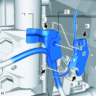
(2) Hook the hook labeled A of the front speed sensor bracket onto the part of the absorber bracket labeled C.
(3) Insert the hook labeled B of the front speed sensor bracket into the part of the absorber bracket labeled D.
| (4) Install the No. 2 front flexible hose and front speed sensor bracket to the absorber bracket with the bolt. Torque: 18.8 N·m {192 kgf·cm, 14 ft·lbf} |
|
.png)
(5) Install the No. 2 front flexible hose to the steering knuckle with the bolt labeled D.
Torque:
18.8 N·m {192 kgf·cm, 14 ft·lbf}
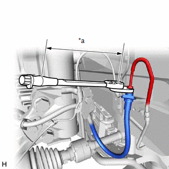
(6) Install a new clip to the front flexible hose.
NOTICE:
Install the clip as far as it will go.
| (7) Using a union nut wrench, connect the brake tube to the front flexible hose while holding the front flexible hose with a wrench. Torque: Specified tightening torque : 15.2 N·m {155 kgf·cm, 11 ft·lbf} HINT:
NOTICE:
|
|
2. CONNECT CABLE TO NEGATIVE AUXILIARY BATTERY TERMINAL
(a) Connect the cable to the negative (-) auxiliary battery terminal and tighten the nut.
Torque:
5.4 N·m {55 kgf·cm, 48 in·lbf}
3. INITIALIZATION AFTER RECONECTING AUXILIARY BATTERY TERMINAL
Click here .gif)
HINT:
When disconnecting and reconnecting the auxiliary battery, there is an automatic learning function that completes learning when the respective system is used.
Click here
4. INSTALL DECK FLOOR BOX LH
Click here
5. INSTALL REAR DECK FLOOR BOX
Click here
6. INSTALL NO. 3 DECK BOARD SUB-ASSEMBLY
Click here
7. BLEED BRAKE LINE
Click here
8. INSTALL FRONT WHEEL
Click here
READ NEXT:
 Components
COMPONENTS ILLUSTRATION *1 DECK FLOOR BOX LH *2 NO. 3 DECK BOARD SUB-ASSEMBLY *3 REAR DECK FLOOR BOX *4 NEGATIVE AUXILIARY BATTERY TERMINAL N*m (kgf*cm, ft.*lbf): Specified
SEE MORE:
Rear Right Sensor Malfunction (C1AE9)
DESCRIPTION The rear corner ultrasonic sensor (RR sensor) is installed to the rear bumper. The clearance warning ECU assembly detects obstacles based on signals received from the rear corner ultrasonic sensor (RR sensor). If the rear corner ultrasonic sensor (RR sensor) has an open circuit or other
Inspection
INSPECTION PROCEDURE 1. INSPECT HEADLIGHT ASSEMBLY LH (a) Apply battery voltage to the connector and check the light illumination condition. OK: Battery Connection Specified Condition Positive (+) → 3 (LO) Negative (-) → 4 (E) Headlight illuminates Positive (+) → 2 (SOL) Neg
