
Lexus NX: Components
COMPONENTS
ILLUSTRATION
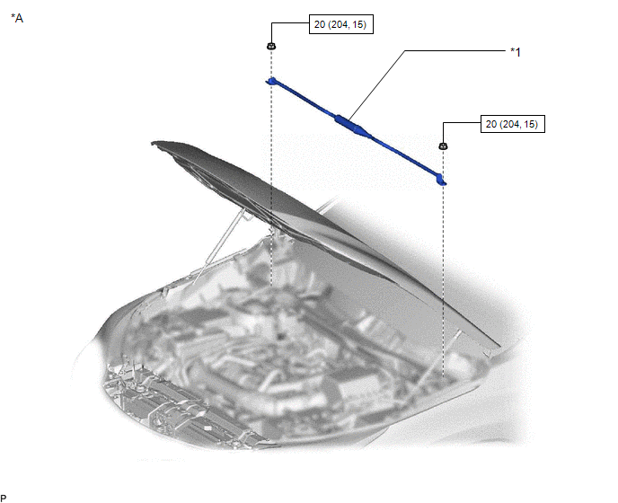 -
-
| *A | w/ Damper | - | - |
| *1 | SUSPENSION TOWER DAMPER | - | - |
.png) | N*m (kgf*cm, ft.*lbf): Specified torque | - | - |
ILLUSTRATION
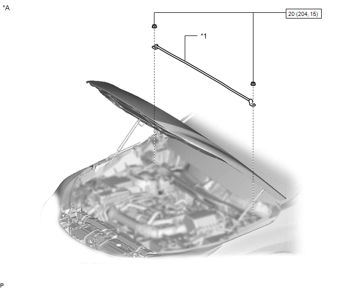 w/ Damper
| *A | w/o Damper | - | - |
| *1 | SUSPENSION TOWER DAMPER | - | - |
| | N*m (kgf*cm, ft.*lbf): Specified torque | - | - |
ILLUSTRATION
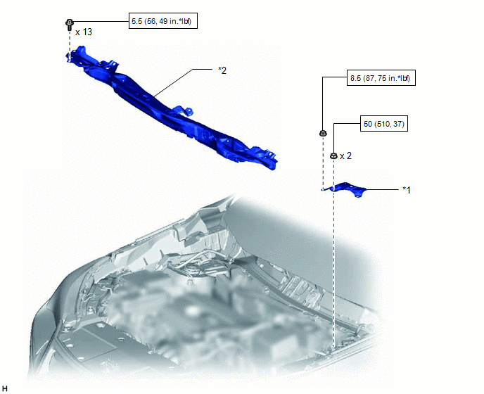
| *1 | COWL BODY MOUNTING REINFORCEMENT LH | *2 | OUTER COWL TOP PANEL |
| | N*m (kgf*cm, ft.*lbf): Specified torque | - | - |
ILLUSTRATION
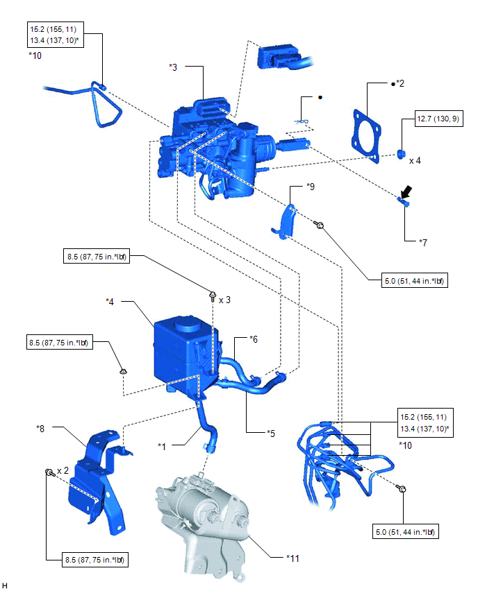
| *1 | BRAKE ACTUATOR HOSE | *2 | BRAKE BOOSTER GASKET |
| *3 | BRAKE BOOSTER WITH MASTER CYLINDER ASSEMBLY | *4 | BRAKE MASTER CYLINDER RESERVOIR ASSEMBLY |
| *5 | NO. 1 RESERVOIR HOSE | *6 | NO. 2 RESERVOIR HOSE |
| *7 | PUSH ROD PIN | *8 | RESERVOIR BRACKET |
| *9 | NO. 2 BRAKE TUBE CLAMP BRACKET | *10 | BRAKE TUBE |
| *11 | BRAKE BOOSTER PUMP ASSEMBLY | - | - |
| | N*m (kgf*cm, ft.*lbf): Specified torque | * | For use with union nut wrench |
| ● | Non-reusable part | .png) | Lithium soap base glycol grease |
READ NEXT:
 Removal
REMOVAL PROCEDURE 1. PRECAUTION CAUTION: Be sure to read Precoution thoroughly before serving. Click here NOTICE: After turning the power switch off, there may be a waiting time before disconnecting
Installation
INSTALLATION PROCEDURE 1. INSTALL BRAKE BOOSTER GASKET (a) Install a new brake booster gasket to the brake booster with master cylinder assembly. 2. INSTALL BRAKE BOOSTER WITH MASTER CYLINDER ASSEMBLY
SEE MORE:
Reassembly
REASSEMBLY CAUTION / NOTICE / HINT HINT:
Use the same procedure for the RH and LH sides.
The procedure listed below is for the LH side.
PROCEDURE 1. INSTALL NO. 3 MOULDING TAPE (a) Clean the No. 3 moulding tape installation surface. (1) When reusing the side mudguard LH, remove the double-si
Automatic High Beam System (B124B)
DESCRIPTION The main body ECU (multiplex network body ECU) determines the status of the automatic high beam system based on the automatic high beam system signal from the forward recognition camera. DTC No. Detection Item DTC Detection Condition Trouble Area B124B Automatic High Beam
© 2016-2026 Copyright www.lexunx.com
