Lexus NX: Reassembly
REASSEMBLY
CAUTION / NOTICE / HINT
HINT:
- Use the same procedure for the RH and LH sides.
- The procedure listed below is for the LH side.
PROCEDURE
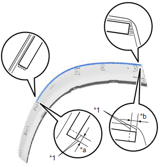
1. INSTALL NO. 5 MOULDING TAPE
(a) Clean the No. 5 moulding tape installation surface with a non-residue solvent.
(b) Apply primer to the No. 5 moulding tape installation area on the quarter outside moulding sub-assembly LH.
NOTICE:
Apply primer evenly so that there are no uncoated areas.
(c) Remove the peeling paper on a new No. 5 moulding tape while making sure not to touch the adhesional surface.
| (d) Install a new No. 5 moulding tape in the position shown in the illustration. NOTICE:
|
|
.png)
2. INSTALL REAR LOWER QUARTER MOULDING PROTECTOR LH
(a) Clean the rear lower quarter moulding protector LH installation surface with a non-residue solvent.
(b) Apply primer to the rear lower quarter moulding protector LH installation area on the quarter outside moulding sub-assembly LH.
NOTICE:
Apply primer evenly so that there are no uncoated areas.
(c) Remove the peeling paper on a new rear lower quarter moulding protector LH while making sure not to touch the adhesional surface.
| (d) Install a new rear lower quarter moulding protector LH in the position shown in the illustration. NOTICE:
|
|
READ NEXT:
 Installation
INSTALLATION CAUTION / NOTICE / HINT PROCEDURE 1. INSTALL QUARTER OUTSIDE MOULDING SUB-ASSEMBLY LH HINT: When installing the quarter outside moulding sub-assembly LH, heat the vehicle body and quarter
Horn
ComponentsCOMPONENTS ILLUSTRATION *1 HIGH PITCHED HORN ASSEMBLY *2 LOW PITCHED HORN ASSEMBLY *3 RADIATOR SUPPORT OPENING COVER - - N*m (kgf*cm, ft.*lbf): Specified torque
SEE MORE:
Engine Hood Courtesy Switch
ComponentsCOMPONENTS ILLUSTRATION *1 HOOD LOCK ASSEMBLY (ENGINE HOOD COURTESY SWITCH) *2 RADIATOR SUPPORT OPENING COVER N*m (kgf*cm, ft.*lbf) : Specified torque MP grease RemovalREMOVAL PROCEDURE 1. REMOVE RADIATOR SUPPORT OPENING COVER Click here 2. REMOVE HOOD LOCK AS
Installation
INSTALLATION PROCEDURE 1. INSTALL GLOVE BOX LIGHT ASSEMBLY (a) Attach the 2 claws to install the glove box light assembly. 2. INSTALL LOWER INSTRUMENT PANEL SUB-ASSEMBLY Click here 3. CONNECT CABLE TO NEGATIVE AUXILIARY BATTERY TERMINAL 4. INITIALIZATION AFTER RECONNECTING AUXILIARY
