Lexus NX: Installation
INSTALLATION
CAUTION / NOTICE / HINT
HINT:
- Use the same procedure for the RH and LH sides.
- The following procedure is for the LH side.
NOTICE:
- Because the RH side flexible hose and LH side flexible hose are not interchangeable, verify the part number when installing the rear flexible hoses.
- If the rear flexible hoses are to be reused, connect them after checking the identification marks placed when each hose was disconnected.
PROCEDURE
1. INSTALL REAR FLEXIBLE HOSE LH
(a) Connect the flexible hose with a new gasket and a new union bolt to the disc brake cylinder.
Torque:
30.4 N·m {310 kgf·cm, 22 ft·lbf}
HINT:
Install the flexible hose lock securely in the lock hole in the cylinder.
(b) Install a new clip to the rear flexible hose.
NOTICE:
Install the clip as far as it will go.
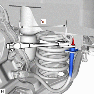
| (c) Using a union nut wrench, connect the flexible hose to the brake tube while holding the flexible hose with a wrench. Torque: Specified tightening torque : 15.2 N·m {155 kgf·cm, 11 ft·lbf} HINT:
NOTICE:
|
|
2. CONNECT CABLE TO NEGATIVE AUXILIARY BATTERY TERMINAL
Click here .gif)
3. INITIALIZATION AFTER RECONECTING AUXILIARY BATTERY TERMINAL
Click here
HINT:
When disconnecting and reconnecting the auxiliary battery, there is an automatic learning function that completes learning when the respective system is used.
Click here
4. INSTALL DECK FLOOR BOX LH
Click here
5. INSTALL REAR DECK FLOOR BOX
Click here
6. INSTALL NO. 3 DECK BOARD SUB-ASSEMBLY
Click here
7. BLEED BRAKE LINE
Click here
8. INSTALL REAR WHEEL
Click here
READ NEXT:
 Replacement
REPLACEMENT CAUTION / NOTICE / HINT HINT:
Use the same procedure for the RH and LH sides.
The following procedure is for the LH side.
NOTICE:
When the brake pedal is first depressed after r
SEE MORE:
Components
COMPONENTS ILLUSTRATION *1 CRANKSHAFT POSITION SENSOR *2 CYLINDER HEAD COVER SUB-ASSEMBLY *3 ENGINE MOUNTING BRACKET RH *4 IGNITION COIL ASSEMBLY *5 CYLINDER HEAD COVER GASKET *6 GASKET *7 SEAL WASHER - N*m (kgf*cm, ft.*lbf): Specified torque ●
Cellular Phone Registration Failure
CAUTION / NOTICE / HINT NOTICE: When replacing the radio receiver assembly, always replace it with a new one. If a radio receiver assembly which was installed to another vehicle is used, the following may occur:
A communication malfunction DTC may be stored.
The radio receiver assembly may not
