Lexus NX: Replacement
REPLACEMENT
CAUTION / NOTICE / HINT
HINT:
- Use the same procedure for the RH and LH sides.
- The following procedure is for the LH side.
NOTICE:
- When the brake pedal is first depressed after replacing the brake pads or pushing back the disc brake piston, DTC C1214 may be output. As there is no malfunction, clear the DTCs.
- While the auxiliary battery is connected, even if the power switch is off, the brake control system activates when the brake pedal is depressed or the door courtesy switch is turned on. Therefore, even if only brake pads are to be removed and installed, be sure to perform the Disable Brake Control procedure and disconnect the cable from the negative (-) terminal of the auxiliary battery before beginning work.
- After replacing the disc brake pads, the clearance between the disc brake pads and rear discs becomes larger and the brake pedal feel becomes softer. Therefore, after replacing the disc brake pads, depress the brake pedal several times and check the clearance and brake pedal feel.
PROCEDURE
1. REMOVE NO. 3 DECK BOARD SUB-ASSEMBLY
Click here .gif)
2. REMOVE REAR DECK FLOOR BOX
Click here
3. REMOVE DECK FLOOR BOX LH
Click here
4. REMOVE REAR WHEEL
Click here
5. REAR BRAKE PAD REPLACEMENT MODE
Click here
6. PRECAUTION
CAUTION:
Be sure to read Precoution thoroughly before serving.
Click here
NOTICE:
After turning the power switch off, there may be a waiting time before disconnecting the negative (-) auxiliary battery terminal.
Click here
7. DISABLE BRAKE CONTROL
Click here
8. DRAIN BRAKE FLUID
NOTICE:
Wash off brake fluid immediately if it comes in contact with any painted surface.
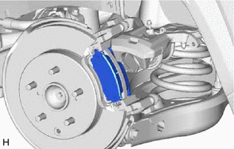
9. REMOVE REAR DISC BRAKE PAD
| (a) Disconnect the connector from the parking brake actuator assembly LH. NOTICE:
|
|
.png)
| (b) Hold the rear disc brake cylinder slide pin and remove the bolt. |
|
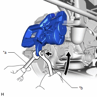
| (c) Lift up the disc brake cylinder assembly as shown in the illustration and remove the rear disc brake pads from the rear disc brake cylinder mounting LH. CAUTION: When removing the rear disc brake pad, make sure that your hands, etc., do not get caught in the disc brake cylinder assembly. |
|
(d) Using a screwdriver, remove the 2 pad wear indicator plates from the rear disc brake pads.
10. REMOVE REAR ANTI-SQUEAL SHIM
(a) Remove the rear No. 1 disc brake anti-squeal shim, rear No. 2 disc brake anti-squeal shim and rear disc brake anti-squeal shim from the rear disc brake pad.
11. INSTALL REAR ANTI-SQUEAL SHIM
(a) Apply disc brake grease to both surfaces of the inner rear No. 1 disc brake anti-squeal shim and only to the inner surface of the outer rear disc brake anti-squeal shim.
.png)
| *a | Inner Side |
| *b | Outer Side |
.png) | Disc brake grease |
NOTICE:
Make sure that disc brake grease is applied onto the lining surface.
| (b) Install the rea No. 1 disc brake anti-squeal shim and rear No. 2 disc brake anti-squeal shim to the rear disc brake pads. NOTICE:
|
|
.png)
(c) Install the rear disc brake anti-squeal shim to the outer rear disc brake pad.
NOTICE:
When replacing a worn pad, the shims must be replaced together with the pads.
12. INSTALL REAR DISC BRAKE PAD
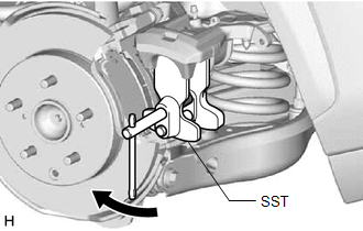
| (a) Using SST, push back the rear disc brake piston. NOTICE: Do not forcibly install the piston into the rear disc brake cylinder. SST: 09719-77010 |
|
(b) Install the 2 new pad wear indicator plates to the rear brake pads.
NOTICE:
Install the pad wear indicator plates in the correct positions and directions.
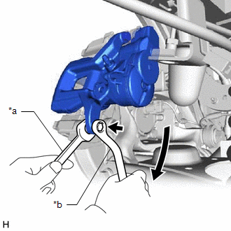
(c) Lift up the disc brake cylinder assembly and install the rear disc brake pads to the rear disc brake cylinder mounting LH.
CAUTION:
When installing the rear disc brake pad, make sure that your hands, etc., do not get caught in the disc brake cylinder assembly.
NOTICE:
Make sure there is no oil or grease on the friction surface of the pads and disc.
HINT:
If the rear disc brake pad has an identification mark, be sure to confirm the installation location.
.png)
| *a | Inner Side (Purple) |
| *b | Outer Side (White) |
| (d) Hold the rear disc brake cylinder slide pin and install the rear disc brake cylinder assembly to the disc brake cylinder mounting with the new bolt. Torque: 34.3 N·m {350 kgf·cm, 25 ft·lbf} |
|
(e) Connect the connector to the parking brake actuator assembly.
(f) Depress the brake pedal several times.
13. ADD BRAKE FLUID
Click here
14. INSTALL REAR WHEEL
Click here
15. CONNECT CABLE TO NEGATIVE AUXILIARY BATTERY TERMINAL
(a) Connect the negative (-) auxiliary battery terminal and tighten the nut.
Torque:
5.4 N·m {55 kgf·cm, 48 in·lbf}
(b) Connect the reservoir level switch connector.
(c) Clear the DTCs.
Click here
16. INITIALIZATION AFTER RECONECTING AUXILIARY BATTERY TERMINAL
Click here
HINT:
When disconnecting and reconnecting the auxiliary battery, there is an automatic learning function that completes learning when the respective system is used.
Click here
17. INSTALL DECK FLOOR BOX LH
Click here
18. INSTALL REAR DECK FLOOR BOX
Click here
19. INSTALL NO. 3 DECK BOARD SUB-ASSEMBLY
Click here
20. RECOVERY TO NORMAL
Click here
READ NEXT:
 Components
COMPONENTS ILLUSTRATION *1 CENTER INSTRUMENT CLUSTER FINISH PANEL ASSEMBLY *2 INSTRUMENT SIDE PANEL LH *3 INSTRUMENT SIDE PANEL RH *4 LOWER NO. 1 INSTRUMENT PANEL FINISH PANEL
SEE MORE:
Parts Location
PARTS LOCATION ILLUSTRATION *1 NO. 2 ENGINE ROOM RELAY BLOCK
- P/SEAT F/R FUSE
*2 INSTRUMENT PANEL JUNCTION BLOCK ASSEMBLY
- P/SEAT F/L FUSE
ILLUSTRATION *A for Driver Side - - *1 LUMBAR SUPPORT ADJUSTER ASSEMBLY LH *2 FRONT LUMBAR POWER SEAT SWITCH *
Diagnosis System
DIAGNOSIS SYSTEM DIAGNOSIS FUNCTION (a) The front camera system does not have a notification function such as a warning light when a DTC is detected. When a malfunction occurs, it stores a DTC and sends it to the systems using the front camera system. The system receiving the malfunction information
