Lexus NX: Components
COMPONENTS
ILLUSTRATION
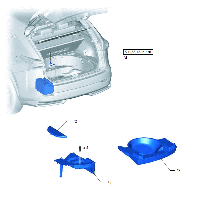
| *1 | DECK FLOOR BOX LH | *2 | NO. 3 DECK BOARD SUB-ASSEMBLY |
| *3 | REAR DECK FLOOR BOX | *4 | NEGATIVE AUXILIARY BATTERY TERMINAL |
.png) | N*m (kgf*cm, ft.*lbf): Specified torque | - | - |
ILLUSTRATION
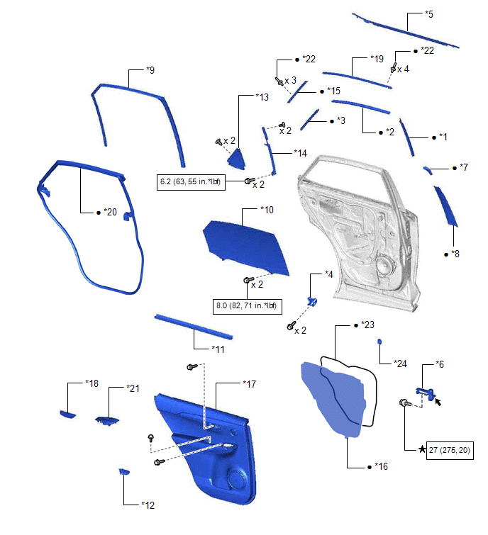
| *1 | NO. 1 BLACK OUT TAPE LH | *2 | NO. 2 BLACK OUT TAPE LH |
| *3 | NO. 3 BLACK OUT TAPE LH | *4 | REAR DOOR ARMREST SET BRACKET LH |
| *5 | REAR DOOR BELT MOULDING ASSEMBLY LH | *6 | REAR DOOR CHECK ASSEMBLY LH |
| *7 | REAR DOOR FRAME GARNISH LH | *8 | REAR DOOR FRONT WINDOW FRAME MOULDING LH |
| *9 | REAR DOOR GLASS RUN LH | *10 | REAR DOOR GLASS SUB-ASSEMBLY LH |
| *11 | REAR DOOR INNER GLASS WEATHERSTRIP LH | *12 | REAR DOOR INSIDE HANDLE BEZEL PLUG LH |
| *13 | REAR DOOR REAR GUIDE SEAL LH | *14 | REAR DOOR REAR LOWER WINDOW FRAME SUB-ASSEMBLY LH |
| *15 | REAR DOOR REAR WINDOW FRAME MOULDING LH | *16 | REAR DOOR SERVICE HOLE COVER LH |
| *17 | REAR DOOR TRIM BOARD SUB-ASSEMBLY LH | *18 | REAR DOOR TRIM COVER LH |
| *19 | REAR DOOR UPPER WINDOW FRAME MOULDING LH | *20 | REAR DOOR WEATHERSTRIP LH |
| *21 | REAR POWER WINDOW REGULATOR SWITCH ASSEMBLY WITH REAR DOOR ARMREST BASE PANEL | *22 | RIVET |
| *23 | BUTYL TAPE | *24 | HOLE PLUG |
| | N*m (kgf*cm, ft.*lbf): Specified torque | ★ | Precoated part |
| ● | Non-reusable part | .png) | MP grease |
READ NEXT:
 Removal
REMOVAL CAUTION / NOTICE / HINT HINT:
Use the same procedure for the RH and LH sides.
The procedure listed below is for the LH side.
PROCEDURE 1. PRECAUTION NOTICE: After the power switch off
Installation
INSTALLATION CAUTION / NOTICE / HINT HINT:
Use the same procedure for the RH and LH sides.
The procedure listed below is for the LH side.
PROCEDURE 1. REPAIR INSTRUCTION Click here 2. INSTAL
SEE MORE:
If your vehicle needs to be towed
If towing is necessary, we recommend
having your vehicle towed by
your Lexus dealer or commercial
towing service, using a wheel-lift
type truck or flatbed truck.
Use a safety chain system for all
towing, and abide by all state/provincial
and local laws.
If towing your vehicle with a whee
Removal
REMOVAL PROCEDURE 1. REMOVE DECK BOARD ASSEMBLY Click here 2. REMOVE NO. 3 DECK BOARD SUB-ASSEMBLY Click here 3. REMOVE REAR DECK FLOOR BOX Click here 4. REMOVE DECK FLOOR BOX LH Click here 5. PRECAUTION CAUTION: Be sure to read Precaution thoroughly before serving. Click here NOTICE: Afte
