Lexus NX: Removal
REMOVAL
CAUTION / NOTICE / HINT
HINT:
- Use the same procedure for the LH side and RH side.
- The following procedure is for the LH side.
PROCEDURE
1. RELEASE PARKING BRAKE
Click here .gif)
2. REMOVE REAR WHEEL
Click here
3. REMOVE NO. 2 TOOL BOX SUB-ASSEMBLY
Click here
4. REMOVE REAR SPEED SENSOR LH (w/ AVS)
| (a) Disconnect the 2 connectors. |
|
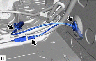
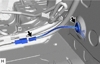
(b) Disconnect the grommet of the rear speed sensor LH from the hole of the wheel house.
| (c) Remove the bolt and sensor clamp from the side member. |
|
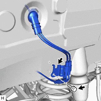
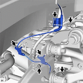
| (d) Disconnect the connector. |
|
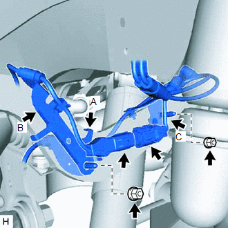
(e) Remove the nut, and then remove sensor clamp A together with sensor clamp B from the upper arm.
(f) Remove the nut and sensor clamp C from the upper arm.
| (g) Remove the nut, and then remove sensor clamp A together with sensor clamp B. |
|
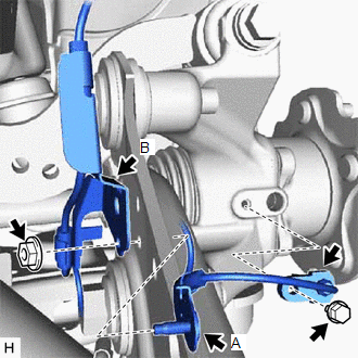
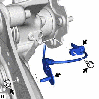
(h) Remove the bolt and rear speed sensor LH.
NOTICE:
Prevent foreign matter from attaching to the rear speed sensor LH tip.
5. REMOVE REAR SPEED SENSOR LH (w/o AVS)
| (a) Disconnect the connector. |
|
(b) Disconnect the grommet of the rear speed sensor LH from the hole of the wheel house.
| (c) Remove the bolt and sensor clamp from the side member. |
|
(d) Remove the 2 nuts and 2 sensor clamps from the upper arm.
| (e) Remove the nut and sensor clamp. |
|
(f) Remove the bolt and rear speed sensor LH from the rear axle carrier.
NOTICE:
Prevent foreign matter from attaching to the rear speed sensor tip.
READ NEXT:
 Installation
INSTALLATION CAUTION / NOTICE / HINT HINT:
Use the same procedure for the LH side and RH side.
The following procedure is for the LH side.
PROCEDURE 1. INSTALL REAR SPEED SENSOR LH (w/ AVS)
Steering Angle Sensor
ComponentsCOMPONENTS ILLUSTRATION *A w/o Steering Heater *B w/ Steering Heater *1 STEERING SENSOR *2 SPIRAL CABLE SUB-ASSEMBLY RemovalREMOVAL PROCEDURE 1. REMOVE SPIRAL W/SENS
SEE MORE:
Automatic High Beam System (B124B)
DESCRIPTION The main body ECU (multiplex network body ECU) determines the status of the automatic high beam system based on the automatic high beam system signal from the forward recognition camera. DTC No. Detection Item DTC Detection Condition Trouble Area B124B Automatic High Beam
ECM Communication Stop Mode
DESCRIPTION Detection Item Symptom Trouble Area ECM Communication Stop Mode Any of the following conditions are met:
Communication stop for "Engine" is indicated on the "Communication Bus Check" screen of the Techstream.
Click here
Communication system DTCs (DTCs that start wit
