Lexus NX: Installation
INSTALLATION
CAUTION / NOTICE / HINT
HINT:
- Use the same procedure for the LH side and RH side.
- The following procedure is for the LH side.
PROCEDURE
1. INSTALL REAR SPEED SENSOR LH (w/ AVS)
| (a) Install the rear speed sensor LH with the bolt. Torque: 8.5 N·m {87 kgf·cm, 75 in·lbf} NOTICE:
|
|
.png)
(b) Install sensor clamp A together with sensor clamp B with the nut.
Torque:
5.0 N·m {51 kgf·cm, 44 in·lbf}
NOTICE:
Do not twist the wire harness for the sensor clamp when installing it.
| (c) Install sensor clamp A together with sensor clamp B with the nut. Torque: 5.0 N·m {51 kgf·cm, 44 in·lbf} NOTICE: Do not twist the wire harness for the sensor clamp when installing it. |
|
.png)
(d) Install sensor clamp C with the nut.
Torque:
5.0 N·m {51 kgf·cm, 44 in·lbf}
NOTICE:
Do not twist the wire harness for the sensor clamp when installing it.
(e) Connect the connector.
(f) Install the sensor clamp to the side member with the bolt.
Torque:
8.5 N·m {87 kgf·cm, 75 in·lbf}
| (g) Insert the connector and grommet into the inside of the vehicle through the passage hole in the wheel house. NOTICE: Make sure the grommet band clamp remains on the outside of the vehicle. |
|
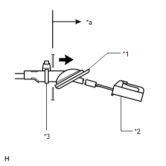
(h) Hold the grommet and pull it toward the outside of the vehicle. Then fix the grommet in place so that it is not tilted.
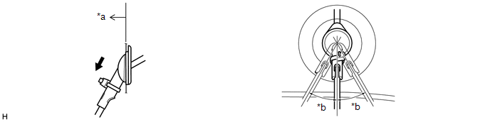
| *a | Outside of Vehicle | *b | 30° |
NOTICE:
- When pulling out the grommet, do not grip the sensor wire.
- Fix the grommet in place within the range shown in the illustration.
(i) Connect the 2 connectors.
2. INSTALL REAR SPEED SENSOR LH (w/o AVS)
(a) Install the rear speed sensor LH with the bolt.
Torque:
8.5 N·m {87 kgf·cm, 75 in·lbf}
NOTICE:
- Prevent foreign matter from attaching to the rear speed sensor tip.
- After installing the speed sensor, make sure there is no clearance or foreign matter between the sensor stay part and the rear axle carrier.
(b) Install the sensor clamp with the nut.
Torque:
5.0 N·m {51 kgf·cm, 44 in·lbf}
(c) Install the 2 sensor clamps to the upper arm with the 2 nuts.
Torque:
5.0 N·m {51 kgf·cm, 44 in·lbf}
NOTICE:
Do not twist the wire harness for the sensor clamp when installing it.
(d) Install the sensor clamp to the side member with the bolt.
Torque:
8.5 N·m {87 kgf·cm, 75 in·lbf}
NOTICE:
Do not twist the wire harness for the sensor clamp when installing it.
| (e) Insert the connector and grommet into the inside of the vehicle through the passage hole in the wheel house. NOTICE: Make sure the grommet band clamp remains on the outside of the vehicle. |
|
(f) Hold the grommet and pull it toward the outside of the vehicle. Then fix the grommet in place so that it is not tilted.
| *a | Outside of Vehicle | *b | 30° |
NOTICE:
- When pulling out the grommet, do not grip the sensor wire.
- Fix the grommet in place within the range shown in the illustration.
(g) Connect the connector.
3. INSTALL NO. 2 TOOL BOX SUB-ASSEMBLY
Click here .gif)
4. INSTALL REAR WHEEL
Click here
5. CHECK FOR SPEED SENSOR SIGNAL
Click here
READ NEXT:
 Steering Angle Sensor
ComponentsCOMPONENTS ILLUSTRATION *A w/o Steering Heater *B w/ Steering Heater *1 STEERING SENSOR *2 SPIRAL CABLE SUB-ASSEMBLY RemovalREMOVAL PROCEDURE 1. REMOVE SPIRAL W/SENS
Components
COMPONENTS ILLUSTRATION *1 CENTER INSTRUMENT CLUSTER FINISH PANEL ASSEMBLY *2 INSTRUMENT SIDE PANEL LH *3 INSTRUMENT SIDE PANEL RH *4 LOWER NO. 1 INSTRUMENT PANEL FINISH PANEL
SEE MORE:
Unable to Unlock Steering Wheel (Hybrid Control System cannot Start)
DESCRIPTION The steering lock actuator assembly activates the steering lock motor and moves the lock bar into the steering column to lock the steering. The steering may not unlock when the lock bar gets stuck in the lock hole of the steering column. In this case, if the power switch is turned on (IG
Lost Communication with Brake System Control Module (U0129,U0293,U1104)
DESCRIPTION The power steering ECU assembly receives signals from the hybrid vehicle control ECU, skid control ECU(brake booster with master cylinder assembly) and forward recognition camera via the CAN communication system. DTC No. Detection Item DTC Detection Condition Trouble Area Warn
