- Unlock Request Receive
- S Code Check
- L Code Check
- Steering Unlock
Lexus NX: Unable to Unlock Steering Wheel (Hybrid Control System cannot Start)
Lexus NX Service Manual / Steering / Steering Column / Steering Lock System / Unable to Unlock Steering Wheel (Hybrid Control System cannot Start)
DESCRIPTION
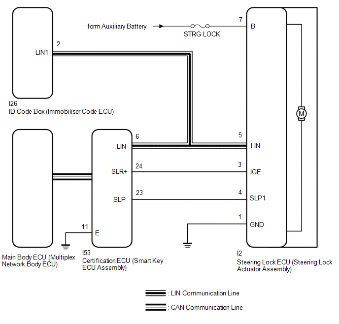
The steering lock actuator assembly activates the steering lock motor and moves the lock bar into the steering column to lock the steering.
The steering may not unlock when the lock bar gets stuck in the lock hole of the steering column. In this case, if the power switch is turned on (IG) while shaking the steering wheel, as is done for a vehicle with a mechanical key, the lock bar will be unlocked. If the certification ECU (smart key ECU assembly), ID code box (immobiliser code ECU) or ECM is replaced, the system needs to be initialized. Otherwise, the steering cannot be unlocked and the hybrid control system cannot be started.
Related Data List and Active Test Items| Problem Symptom | Data List Item | Active Test Item |
|---|---|---|
| Unable to unlock steering wheel (Hybrid control system cannot start) | Smart Access | - |
WIRING DIAGRAM
CAUTION / NOTICE / HINT
NOTICE:
- When using the Techstream with the power switch off, connect the Techstream to the vehicle and turn a courtesy light switch on and off at intervals of 1.5 seconds or less until communication between the Techstream and the vehicle begins. Then select the vehicle type under manual mode and enter the following menus: Body Electrical / Smart Access. While using the Techstream, periodically turn a courtesy light switch on and off at intervals of 1.5 seconds or less to maintain communication between the Techstream and the vehicle.
-
Perform either of the following operations to lock/unlock the steering:
- To unlock the steering, carry the key and turn the power switch on (ACC) or on (IG) with the shift lever in P.
- To lock the steering, turn the power switch off with the shift lever in P, and then open a door.
-
The steering lock system uses LIN communication. First perform the inspections in "How to Proceed with Troubleshooting" to confirm that there are no communication malfunctions before proceeding with troubleshooting.
Click here
.gif)
- After performing repairs, confirm that the problem does not recur.
-
Make sure that no DTCs are output. If any DTCs are output, proceed to the Diagnostic Trouble Code Chart.
Click here
- Inspect the fuses for circuits related to this system before performing the following procedure.
-
When replacing the steering lock ECU (steering lock actuator assembly), certification ECU (smart key ECU assembly) or ID code box (immobiliser code ECU), registration must be performed.
Click here
- If the steering lock ECU (steering lock actuator assembly) is replaced, be sure to confirm that the steering is unlocked by turning the steering wheel to the left and right before starting the hybrid control system. This function prevents the hybrid control system from starting while the steering is locked. If the steering is locked for any reason, open and close a door with the power switch off, and then unlock the steering by pressing the power switch.
-
After the power switch is turned off, there may be a waiting time before disconnecting the negative (-) auxiliary battery terminal.
Click here
-
When disconnecting and reconnecting the auxiliary battery
Click here
HINT:
When disconnecting and reconnecting the auxiliary battery, there is an automatic learning function that completes learning when the respective system is used.
Click here
PROCEDURE
| 1. | CHECK POWER SWITCH (SWITCH CONDITION) |
(a) Check the power source mode change.
(1) When the key is inside the vehicle and the shift lever is in P, check that pressing the power switch with the brake pedal released causes the power source mode to change as follows:
OK:
Off → On (ACC) → On (IG) → Off
| NG | .gif) | GO TO SMART ACCESS SYSTEM WITH PUSH-BUTTON START (for Start Function) (PROBLEM SYMPTOMS TABLE) |
|
.gif)
| 2. | CHECK INDICATOR |
(a) With the power switch on (IG), check that Steering Lock active is displayed on the multi-information display in the combination meter assembly.
| Result | Proceed to |
|---|---|
| Steering Lock active is displayed. | A |
| Steering Lock active is not displayed. | B |
| B | | GO TO STEP 4 |
|
| 3. | CHECK STEERING UNLOCK |
(a) While turning the steering wheel left and right, press the power switch.
(b) Check that the steering is unlocked.
| Result | Proceed to |
|---|---|
| The steering is unlocked. | A |
| The steering is not unlocked. | B |
| A | | END |
|
| 4. | CHECK FOR DTC |
(a) Using the Techstream, check if the certification ECU (smart key ECU assembly) DTC is output.
Body Electrical > Smart Access > Trouble Codes Body Electrical > Power Source Control > Trouble Codes| Result | Proceed to |
|---|---|
| DTCs are not output. | A |
| DTCs are output. | B |
| B | | GO TO DIAGNOSTIC PROCEDURE INDICATED BY OUTPUT DTC |
|
| 5. | READ VALUE USING TECHSTREAM (UNLOCK REQUEST RECEIVE) |
(a) Use the Data List to check if the steering lock request is functioning properly.
Body Electrical > Smart Access > Data List| Tester Display | Measurement Item | Range | Normal Condition | Diagnostic Note |
|---|---|---|---|---|
| Unlock Request Receive | Unlock request signal received state | OK or NG | OK: Unlock request signal received within 10 seconds of power switch on (IG) or on (ACC), or of a hybrid control system start operation being performed NG: Power switch not turned on (IG) or on (ACC), and hybrid control system start operation not performed |
|
| Tester Display |
|---|
| Unlock Request Receive |
OK:
Within 10 seconds of turning the power switch on (ACC) or on (IG) or starting the hybrid control system, the Data List item changes to "OK".
| NG | | GO TO STEP 15 |
|
| 6. | READ VALUE USING TECHSTREAM (S CODE CHECK) |
(a) Use the Data List to check if S code certification is functioning properly.
Body Electrical > Smart Access > Data List| Tester Display | Measurement Item | Range | Normal Condition | Diagnostic Note |
|---|---|---|---|---|
| S Code Check | Verification result between certification ECU (smart key ECU assembly) and ID code box (immobiliser code ECU) | OK or NG | OK: Verification result normal NG: Verification result abnormal | When NG is displayed:
|
| Tester Display |
|---|
| S Code Check |
OK:
OK is displayed on the Techstream.
HINT:
Reasons for verification failure:
- The certification ECU (smart key ECU assembly) or ID code box (immobiliser code ECU) is malfunctioning.
- There is a problem with the communication between ECUs.
- An ECU is replaced, but is not registered.
- An ECU is replaced with an ECU which has a code already stored in it.
| NG | | GO TO STEP 14 |
|
| 7. | READ VALUE USING TECHSTREAM (L CODE CHECK) |
(a) Use the Data List to check if L code certification is functioning properly.
Body Electrical > Smart Access > Data List| Tester Display | Measurement Item | Range | Normal Condition | Diagnostic Note |
|---|---|---|---|---|
| L Code Check | Verification result between ID code box (immobiliser code ECU) and steering lock ECU (steering lock actuator assembly) | OK or NG | OK: Verification result normal NG: Verification result abnormal | When NG is displayed:
|
| Tester Display |
|---|
| L Code Check |
OK:
OK is displayed on the Techstream.
HINT:
Reasons for verification failure:
- The steering lock ECU (steering lock actuator assembly) or ID code box (immobiliser code ECU) is malfunctioning.
- There is a problem with the communication between ECUs.
- An ECU is replaced, but is not registered.
- An ECU is replaced with an ECU which has a code already stored in it.
| NG | | GO TO STEP 11 |
|
| 8. | INSPECT STEERING LOCK ECU (STEERING LOCK ACTUATOR ASSEMBLY) |
| (a) Measure the resistance and voltage according to the value(s) in the table below. Standard Resistance:
NOTICE: If the result is not as specified, check for looseness in the ground cable connection. Standard Voltage:
|
|
| NG | | REPAIR OR REPLACE HARNESS OR CONNECTOR |
|
| 9. | CHECK HARNESS AND CONNECTOR (GROUND) |
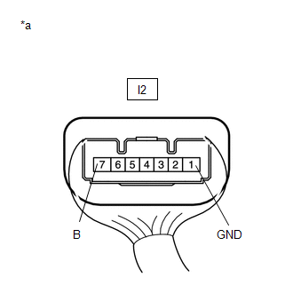
(a) Disconnect the I2 steering lock ECU (steering lock actuator assembly) connector.
| (b) Measure the resistance according to the value(s) in the table below. Standard Resistance:
|
|
.png)
| NG | | REPAIR OR REPLACE HARNESS OR CONNECTOR |
|
| 10. | INSPECT STEERING LOCK ECU (STEERING LOCK ACTUATOR ASSEMBLY) |
(a) Reconnect the I2 steering lock ECU (steering lock actuator assembly) connector.
| (b) Check the signal waveform according to the condition(s) in the table below. Standard Frequency:
HINT:
|
|
.png)
| Result | Proceed to |
|---|---|
| OK (for Manual tilt and manual telescopic steering column) | A |
| OK (for Power tilt and power telescopic steering column) | B |
| NG | C |
| A | | REPLACE STEERING LOCK ECU (STEERING LOCK ACTUATOR ASSEMBLY) |
| B | | REPLACE STEERING LOCK ECU (STEERING LOCK ACTUATOR ASSEMBLY) |
| C | | GO TO STEP 12 |
| 11. | REPLACE STEERING LOCK ECU (STEERING LOCK ACTUATOR ASSEMBLY) |
(a) Replace the steering lock ECU (steering lock actuator assembly) with a new one.
for Manual tilt and manual telescopic steering column: Click here
(b) Replace the steering lock ECU (steering lock actuator assembly) with a new one.
for Power tilt and power telescopic steering column: Click here
(c) Perform registration procedures.
Click here
(d) Turn the power switch on (IG).
(e) Use the Data List to check if L code certification is functioning properly again.
Body Electrical > Smart Access > Data List| Tester Display | Measurement Item | Range | Normal Condition | Diagnostic Note |
|---|---|---|---|---|
| L Code Check | Verification result between ID code box (immobiliser code ECU) and steering lock ECU (steering lock actuator assembly) | OK or NG | OK: Verification result normal NG: Verification result abnormal | When NG is displayed:
|
| Tester Display |
|---|
| L Code Check |
OK:
OK is displayed on the Techstream.
| OK | | END |
| NG | | REPLACE ID CODE BOX (IMMOBILISER CODE ECU) |
| 12. | CHECK HARNESS AND CONNECTOR (STEERING LOCK ECU (STEERING LOCK ACTUATOR ASSEMBLY) - CERTIFICATION ECU (SMART KEY ECU ASSEMBLY)) |
(a) Make sure that there is no looseness at the locking part and the connecting part of the connectors.
(b) Disconnect the I2 steering lock ECU (steering lock actuator assembly) connector.
(c) Disconnect the I53 certification ECU (smart key ECU assembly) connector.
(d) Check for deformation and corrosion of the connector case and terminals.
OK:
There is no deformation or corrosion of the connector case or terminals.
(e) Measure the resistance according to the value(s) in the table below.
Standard Resistance:
| Tester Connection | Condition | Specified Condition |
|---|---|---|
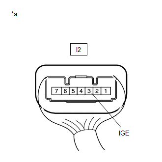
| I2-3 (IGE) - I53-24 (SLR+) | Always | Below 1 Ω |
| I2-3 (IGE) or I53-24 (SLR+) - Body ground | Always | 10 kΩ or higher |
| NG | | REPAIR OR REPLACE HARNESS OR CONNECTOR |
|
| 13. | INSPECT STEERING LOCK ECU (STEERING LOCK ACTUATOR ASSEMBLY) |
(a) Reconnect the I2 steering lock ECU (steering lock actuator assembly) connector.
(b) Reconnect the I53 certification ECU (smart key ECU assembly) connector.
| (c) Measure the voltage according to the value(s) in the table below. Standard Voltage:
|
|
| Result | Proceed to |
|---|---|
| OK | A |
| NG (for Manual tilt and manual telescopic steering column) | B |
| NG (for Power tilt and power telescopic steering column) | C |
| A | | REPLACE CERTIFICATION ECU (SMART KEY ECU ASSEMBLY) |
| B | | REPLACE STEERING LOCK ECU (STEERING LOCK ACTUATOR ASSEMBLY) |
| C | | REPLACE STEERING LOCK ECU (STEERING LOCK ACTUATOR ASSEMBLY) |
| 14. | REPLACE CERTIFICATION ECU (SMART KEY ECU ASSEMBLY) |
(a) Replace the certification ECU (smart key ECU assembly) with a new one.
Click here
(b) Perform registration procedures.
Click here
(c) Use the Data List to check if S code certification is functioning properly.
Body Electrical > Smart Access > Data List| Tester Display | Measurement Item | Range | Normal Condition | Diagnostic Note |
|---|---|---|---|---|
| S Code Check | Verification result between certification ECU (smart key ECU assembly) and ID code box (immobiliser code ECU) | OK or NG | OK: Verification result normal NG: Verification result abnormal | When NG is displayed:
|
| Tester Display |
|---|
| S Code Check |
OK:
OK is displayed on the Techstream.
| OK | | END |
| NG | | REPLACE ID CODE BOX (IMMOBILISER CODE ECU) |
| 15. | INSPECT STEERING LOCK ECU (STEERING LOCK ACTUATOR ASSEMBLY) |
| (a) Measure the voltage according to the value(s) in the table below. Standard Voltage:
|
|
| NG | | GO TO STEP 18 |
|
| 16. | READ VALUE USING TECHSTREAM (STEERING UNLOCK) |
(a) Check that the steering is locked.
(b) Read the Data List according to the display on the Techstream.
Body Electrical > Smart Access > Data List| Tester Display | Measurement Item | Range | Normal Condition | Diagnostic Note |
|---|---|---|---|---|
| Steering Unlock | Steering lock ECU (steering lock actuator assembly) unlock confirmation status | Unset or Set | Unset: Unlock not confirmed Set: Unlock confirmed | When Unset is displayed, the steering is not unlocked (the hybrid control system cannot be started). |
| Tester Display |
|---|
| Steering Unlock |
OK:
"Set" is displayed on the Techstream.
| Result | Proceed to |
|---|---|
| OK | A |
| NG (for Manual tilt and manual telescopic steering column) | B |
| NG (for Power tilt and power telescopic steering column) | C |
| B | | REPLACE STEERING LOCK ECU (STEERING LOCK ACTUATOR ASSEMBLY) |
| C | | REPLACE STEERING LOCK ECU (STEERING LOCK ACTUATOR ASSEMBLY) |
|
| 17. | READ VALUE USING TECHSTREAM (UNLOCK REQUEST RECEIVE) |
(a) Replace the certification ECU (smart key ECU assembly) with a new one.
Click here
(b) Perform registration procedures.
Click here
(c) Turn the power switch on (IG).
(d) Use the Data List to check if the steering lock request is functioning properly.
Body Electrical > Smart Access > Data List| Tester Display | Measurement Item | Range | Normal Condition | Diagnostic Note |
|---|---|---|---|---|
| Unlock Request Receive | Unlock request signal received state | OK or NG | OK: Unlock request signal received within 10 seconds of power switch on (IG) or on (ACC), or of a hybrid control system start operation being performed NG: Power switch not turned on (IG) or on (ACC), and hybrid control system start operation not performed |
|
| Tester Display |
|---|
| Unlock Request Receive |
OK:
Within 10 seconds of turning the power switch on (ACC) or on (IG) or starting the hybrid control system, the Data List item changes to "OK".
| OK | | END |
| NG | | REPLACE ID CODE BOX (IMMOBILISER CODE ECU) |
| 18. | CHECK HARNESS AND CONNECTOR (STEERING LOCK ECU (STEERING LOCK ACTUATOR ASSEMBLY) - CERTIFICATION ECU (SMART KEY ECU ASSEMBLY)) |
(a) Make sure that there is no looseness at the locking part and the connecting part of the connectors.
(b) Disconnect the I2 steering lock ECU (steering lock actuator assembly) connector.
(c) Disconnect the I53 certification ECU (smart key ECU assembly) connector.
(d) Check for deformation and corrosion of the connector case and terminals.
OK:
There is no deformation or corrosion of the connector case or terminals.
(e) Measure the resistance according to the value(s) in the table below.
Standard Resistance:
| Tester Connection | Condition | Specified Condition |
|---|---|---|
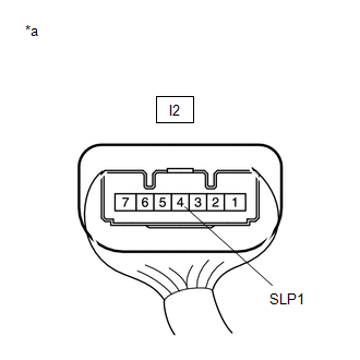
| I2-4 (SLP1) - I53-23 (SLP) | Always | Below 1 Ω |
| I2-4 (SLP1) or I53-23 (SLP) - Body ground | Always | 10 kΩ or higher |
| NG | | REPAIR OR REPLACE HARNESS OR CONNECTOR |
|
| 19. | READ VALUE USING TECHSTREAM (UNLOCK REQUEST RECEIVE) |
(a) Replace the steering lock ECU (steering lock actuator assembly) with a new one.
for Manual tilt and manual telescopic steering column: Click here
(b) Replace the steering lock ECU (steering lock actuator assembly) with a new one.
for Power tilt and power telescopic steering column: Click here
(c) Perform registration procedures.
Click here
(d) Turn the power switch on (IG).
(e) Use the Data List to check if the steering lock request is functioning properly.
Body Electrical > Smart Access > Data List| Tester Display | Measurement Item | Range | Normal Condition | Diagnostic Note |
|---|---|---|---|---|
| Unlock Request Receive | Unlock request signal received state | OK or NG | OK: Unlock request signal received within 10 seconds of power switch on (IG) or on (ACC), or of a hybrid control system start operation being performed NG: Power switch not turned on (IG) or on (ACC), and hybrid control system start operation not performed |
|
| Tester Display |
|---|
| Unlock Request Receive |
OK:
Within 10 seconds of turning the power switch on (ACC) or on (IG) or starting the hybrid control system, the Data List item changes to "OK".
| OK | | END |
| NG | | REPLACE CERTIFICATION ECU (SMART KEY ECU ASSEMBLY) |
READ NEXT:
 Steering Lock does not Lock
DESCRIPTION The steering lock actuator assembly activates the steering lock motor and moves the lock bar into the steering column to lock the steering. When the steering lock is operating, the steerin
Components
COMPONENTS ILLUSTRATION *1 CRUISE CONTROL MAIN SWITCH *2 STEERING PAD SWITCH ASSEMBLY
SEE MORE:
Only Back Door cannot be Opened
DESCRIPTION The main body ECU (multiplex network body ECU) receives signals from the back door opener switch assembly. Then, the main body ECU (multiplex network body ECU) activates the back door lock motor. WIRING DIAGRAM CAUTION / NOTICE / HINT NOTICE:
When using the Techstream with the vehicl
Terminals Of Ecu
TERMINALS OF ECU DCM (TELEMATICS TRANSCEIVER) Click here RADIO RECEIVER ASSEMBLY Click here NAVIGATION ECU Click here
© 2016-2026 Copyright www.lexunx.com
